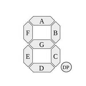
2 x 7 segment displays


#1

Hello,

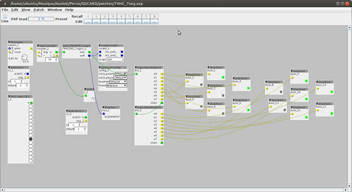
I made an object to drive 2 seven segment displays (0 - 99) with 2x 74HC595.


The object:74HC595_7segmentsx2.axo (1.3 KB)

The patch with the script needed for the 74HC595: 74HC_7seg.axp (7.5 KB)

And a version of the object for only one display:74HC595_7segments.axo (1.3 KB)


#3

Hi,

I don't know what's going wrong.

I'm on 1.0.10

74HC595_7segmentsx2.axo is in my axoloti folder under objects/gpio


#4

Now the object is in the library under gpio, with 1.0.10


#5

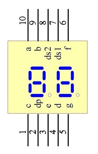
I got an dual 7 segment like this here

What would be the best way to interface this?


#6

I don't know... I think this one is not a 7 segments but 14 or 16


#7

Do you have a link to a datasheet ?


#8

not really,(nfd-5621as-41) the picture u see is how it works, maybe someone else can explain? i cant even imagine how that would work ...ds 1 and ds2 is an 2bit input for toggeling between first number and second number, there are also 3 digit 7 segment displays wich could display 127/256. i wonder how these work...


#9

Found that:
http://www.tme.eu/fr/Document/1bc8baff257493c28149daeeb5947c49/LD-D056X.pdf


#10

i found that too , but it still remains uncomprehensable.....


#11

For me too, sorry....
Is my patch working for you now?


#12

yes i got one digit working! I stll wonder about the connections ...q0 = a q1 = b .......and q8 is dot?


#13

Sorry I don't have the time
For me it's working like this:

q0 = G
q1 = E
q2 = D
Q3 = C
Q4 = B
Q5 = A
Q6 = F

Or GFEDCBE .... I don't remember

Q7 is the dot but I don't have one


#14

Thank you very much!!
i found this for my dual digit display:

The strange thing is this was used for a track number display for a

CD so both 7 seg's must have been controlled differently. Pin 7 when +
turns on the right screen and Pin 8 + turns on the left screen. When
both are + both screens go on. Whenever I change the other pins they
change both screens so I am confused as to how to change each screen
individually. Pin 2 when - is the d.p. Each Pin is an annode because it
is only affected when in the - side. I believe I am describing this
correctly. Sorry I am not very familiar with describing it other ways.

So it sounds like each digit is configured with a common cathode (-
side), with the two CC pins providing multiplex access to the digits.
Each of the pairs of 7 segments share an anode pin. So your drive
circuit will need to drive the two digits in an alternating fashion,
with each digit being on for 1/2 of the time. Drive them above the
flicker fusion frequency of the human eye -- something like 50Hz should
be fast enough, but you can experiment.

Reference https://www.physicsforums.com/threads/10-pin-dual-7-segment-display-cant-find-documentation.331089/

#15

ummmm seems i have deleted ur object, seems unlikley, but happend.....