Using tables to create a polyphonic sample-based drum with different kits


#1

piezo-drum-test-X2.axp (10.7 KB)
piezo-drum-test.axp (4.9 KB)
Hi everyone! I´m developing a six voice polyphonic sample-based and piezo-triggered drum module. The idea is that you can change the complete 6 sounds (a "kit") by using a button. It works like a charm using one table but as soon as I use a second one, either it goes mute or both samplers play the same file.
The structure of filenames for each kit would be:
kit 1:
000.raw
010.raw
020.raw
to 050.raw

kit 2:
001.raw
011.raw
021.raw
to 051.raw

and so on.

In the first example, everything works great. I use both included buttons, one to change samples and the other to trigger them. In the second example, I have two tables, with different names and another digital pin to trigger the second sound but it triggers the same sound as the first table. I attach the files in raw in case anyone wants to try it.
Thanks a lot in advance

#2

Here´s a link to download the samples
https://drive.google.com/open?id=1Wb1cJFwI29kkUq1n8y_OLuQ20mocfLJi


#3

Sorry I cannot download your samples (no permission for google drive).
Anyway your patch looks right at first sight,
The only weird thing I see is two objects 'GPIO in' for the same button...
You only need 1 GPIO button1 object, just connect it to both counter1 and counter2.
I hope this helps!


#4

Also in your patch you are doing +20 for the second sample, it should be +10 if you want the second sample to be 010.raw.
In your patch above it's going to look for 020.raw!


#5

Hi, Andrew, thanks for your advice in not using duplicated objects. I just didn´t noticed that.
Don´t know what happened in the first place but now the original patch I made works great!. You were right.
Here´s the patch.ludo-sample-drum.axp (76.7 KB)
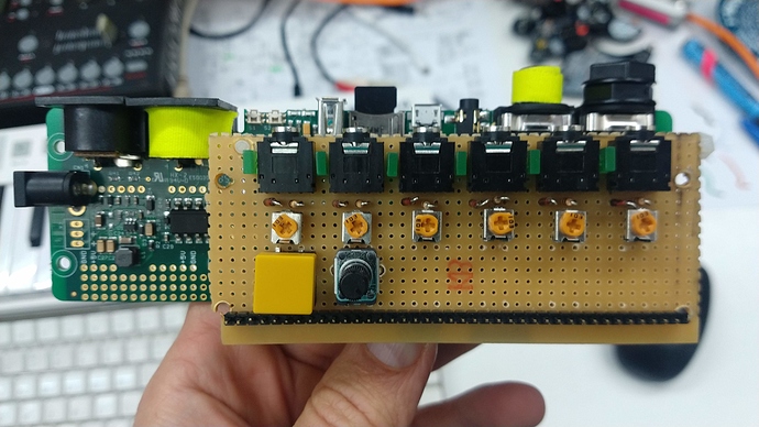
and a picture of the circuit:


It has 6 channels, each of them with a 3.5" connector for the piezos, protected with 3.3V zener diodes and also with a 1M pull-dow resistor.
It also has a 10k trimpot per channel for adjusting sensitivity and a led to show when a sample is triggered.
Finally a button for changing banks upwars cyclically (now working with only 3 but it can be easily change) and a potentiometer for the main volume.
As soon as I have time, I´ll design a pcb and ulpoad the schematics.
Hope this wlll be useful for some one else.