Hi and thanks a lot for the description of you project, very instructive.
I would like to quickly try it before working on my own wavetable files. Would it be possible for you to reupload your pack?
Thank you!
The Xylobox Wavetable Synthesizer (hardware + patches)
SPI Problems with MCP3008 and MCP23s17
Hello,
Sorry for the long delay! I've been apprised of the downed link and fixed the link to the wavetable files, you can get them here!
http://matthewcieplak.com/dd/instruments/wt.zip
A backup link is here:
https://drive.google.com/drive/folders/1jAx05oj_oWoyeeOyhWAcNhijK9UnTGtq?usp=sharing
Hey Matthew,
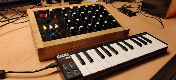
Thanks for this great project. Decided to build one. It was quite a journey (I am not a coder)  So, it is finished (sorta). The top-plate is a home (mpcnc) routed one and scratched. I am waiting till my local Fablab is open again (closed due to C19), so I can lasercut/etch one.
Thing I changed:
- Added third MCP3008
- Changed the 23s17 to a I2C one due to compatibiltyproblems with 3 MCP3008's
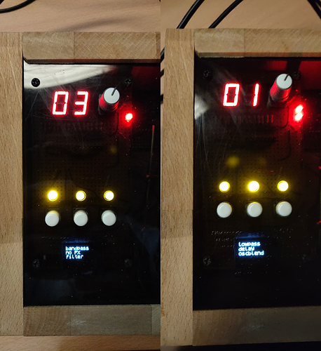
- Added a I2C OLED display I had laying around. This gives the active values of the 3 buttons.
- Push the encoder to change which osc to change. The 2 leds right to the encoder indicate which table I change and Which oscilator you see on the display.
- All 3 LEDs are on a PWM channel and vary brightness on each value.
Love it!
Help advise a total and complete beginner on how to build my enclosure!
2 Axoloti machines for sale (Sold)
Wow, that's really amazing! Great idea to add a screen for the buttons. Keeps the interface minimal but usable without menu-diving. And I think you've improved a little on my woodworking joinery as well 
The push encoder thing is a good touch, tweaking the morph knob to select was always a little hackish.
Have heard good things about I2C but still stuck in my serial ways for the most part - I can see why the switch makes sense. I'm sure people would appreciate seeing your patches to see how you've implemented it as well.
I2C is serial indeed, invented by Philips  Actualy it is IIC = Inter IC bus. One improvement I want to implement is to turn the filter off. Already seen how this most be done, something to do coming weekend.
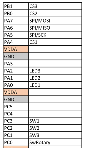
I indeed forgot to add the patches. included is also a sheet with the GPIO connections. Here they are.
stereo_delay.axs (9.2 KB)
master_patch.axp (22.2 KB)
vowel_filter.axs (15.4 KB)
wavetable_voice.axs (35.8 KB)
xylobox_control.axs (30.0 KB)
Patches with posibility to turn filter off:
stereo_delay.axs (9.2 KB)
wavetable_voice.axs (35.8 KB)
master_patch.axp (24.5 KB)
xylobox_control.axs (31.4 KB)
vowel_filter.axs (15.4 KB)
Have fun with them 
hello Matthew,
I really dig your design and would love to replicate it with some twists. I just have a question regarding the wiring schematics. I observed that you hooked the mcp's to a 5V source (I assume sourcing from the 5V supply pin present on the Axoloti). Are the D_Out pins from the ADCs at 3.3V or 5V voltage level? I spent some time reading up on forums and studying the mcp3008 data sheet but couldn't figure this out.
Cool, thanks for the answer. According to the datasheet you can use 3.3/5V and the only affected characteristic is the sampling rate in ksps as I understood. The question was more regarding how this was solved in the original xylobox design, since the schematics show a direct connection from the mcp3008 to the Axoloti pins, while the mcps are powered with 5V. I don't know if the communication pin voltage level relates to the source and reference voltages or if it stays at 3.3v independently of Vdd and Vref.
Well, if it works, it works. The 3008's give a digital value back which is a measurement of the Vpot to the VRef. So it should not matter... Communication is related to Vdd, but as stated here almost al of the Axoloti's GPIO pins should be 5v tolerant.
But as you said, perhaps @matthewcieplak can shine his lights...

