I’ll have to keep searching, bought these for a eurorack build sometime ago
SPI/I2C OLED display
Maybe, somebody here has experimented with similar displays and will give you some advice.
If not I just ordered a couple correct OLEDs on-line. I’ll be up and running in a few days. Thanks for your input and contributions to the community
Managed to convert my spi to i2c! Got the first one working perfectly. Trying to use your double object but seem stuck. Do both OLEDs use the same pin outs from the axo? Just use jumpers to the other? Or are they hooked to a different set of outputs?
Good news !
They should be connected on the same pins but have different I2C addresses.
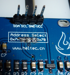
On many devices the I2C address can be changed by adding a strap.
Strap?. can you take a picture of your displays?. I just got a first display working btw. Thank you very much!.
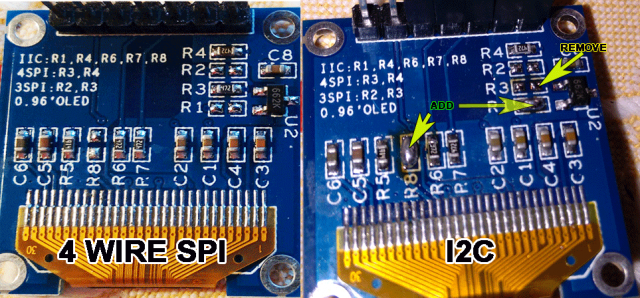
Thank you sir! If anyone else has these types of displays here is the info that got me where I needed to go....
You simply bridge the resistors needed and remove the resistors not needed for your wanted use.
Mine were not these exact type but had the same listing on the back which I didn’t even notice were there.
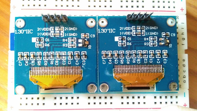
this is how my displays look from the back.. I guess I'm close but I can't be 100% sure about which resistor should I move without checking schematics/ spreadsheet :
I have not seen resistors in your first photos. Why do you said in your description later that you are adding "two 10k pull up resistors from PB8 and PB9 to VDD"? I really want to add an oled to my projects and this will be very heplfull. Thanks in advance!
Hi, @xoanxil,
The I2C needs pull ups resistors.
On my first pictures, they you can see them on the breadboard, even if they are somewhat hidden by wires, they are there.
Teah. I can see them How do you conect. How do I should conect them?
PB8 connects to SCL
PB9 connects to SDA
VDD connects to VCC
GND connects to GND
PB8 connects to 10k resistor and to VDD?
PB9 connects to 10k resistor and to VDD?
What does it happen if I don´t use resitors?
Thanks for your help
Hey smashed, been playing with the single screen object today. My wave form only displays in the top 1/3 of the screen and is severely clipped. Can you give me a hint as to where to optimize the display settings? Also, using your scope in the community library, is it possible to have 4 separate wave forms display in one scope. I’d like to be able to have 4 Osc waves displayed on the same OLED.
Did you tried the help patch (Help -> Library -> Community -> tiar ->HW -> OLED128x64) ?
The object i coded can only display one scope.
Did you try to select the type to SH1106 or to SD1136, these are the different OLED control chips often found on 0.96 or 1.31 displays. Do you have info about the control chip driving your OLED display ?
So, quick answer, I don't know, it certainly depends on your displays (it seems that some include pull up resistors).
Help file worked like a charm! Thank you! Also had a run with the reminder object. It works like a charm. I tired editing the object for personal use in a patch with more than 4 inputs but couldn’t figure out how to do it. Is this possible?
@johannes had a great idea when implementing help pages, this is a nice way of documenting objects.
The OLED128x64 has only 4 inputs corresponding to 4 lines.
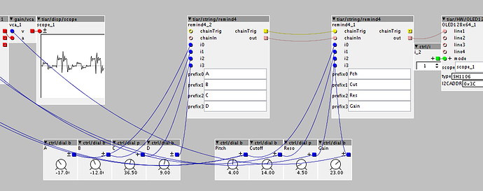
The remind4 can now be chained (since i updated the library).
The "chainTrig" boolean signals tells the next remind4 in the chain "hey, buddy, i've got something, please take my input and transmit it to your output".
Thank you SmashedTransistors for the explanation. I will use the resistors just in case.
Should I conect then PB8 connects to 10k resistor and to VDD and PB9 connects to 10k resistor and to VDD?
Do not connect directly PB8 nor PB9 directly to VDD.
PB8 is pulled up to VDD through a resistor.
PB9 is pulled up to VDD throuch another resistor.


