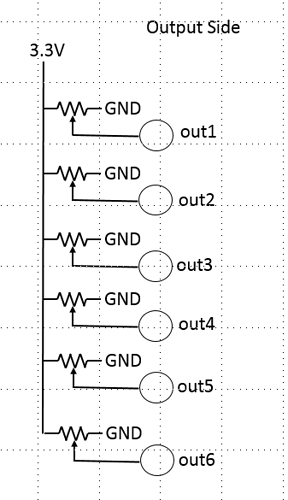
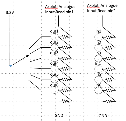
I have considered this idea before, actually inspired by the MS20-ic
in my idea, this was solely for patching 'on the fly' within axoloti .. I'll come back to this later, as I'm not sure if this is your goal or not (as bastls approach allows for other devices to get involved)
my approach:
i considered this actually as mainly a software problem (perhaps because I'm a software guy  ) , basically the GPIO , would just connect digital OUT to digital IN(s) , and then each digital out woud send a unique digital signature , such that the input would know to which output it was connected.
for patching, I was then just going to create an input and output objects, a bit like the send and receive objects... but which would be gated/routed according to the current physical connections.
your approach is different... (my understanding could be incorrect, so bare with me  )
)
I guess you must still be using digital outs... as there are only 2 analog outs.
in which case, you still end up with a essentially a switch... but your using the voltage as a signature.
... one question, won't the voltage change, if you have 2 outputs connected to 2 different inputs?
as the 3.3v will now be divided thru two different paths?
(i.e. OUT 5 -> IN 5 = X volts, but when you in addition connect OUT1 -> IN1 , is the O5I5 still X?)
I guess this could be avoided if you essentially scan the outputs, or perhaps you can just calculate this, as its still a constant... perhaps you covered this above, but I just missed it.
internal midi, yeah nice if you want to have easy, CC mapping, but it does limit you to 7 bit, and its also not at audio rate. (which I think was the point you were making about s-rate link)
'on the fly within axoloti' ... so another approach its to go the whole 'cv' approach, and just make it a 3.3v voltage... this would allow other devices (or even multiple axoloti) to join in the fun... as the signal is not just a routing switch, but a real signal (this is what bastl do)
Ive actually made up some boards which allow, this but using 5v, so I can interface to an AE modular, and other BASTL stuff which is 5v, which was the primary advantage of this approach as i saw it.
the main issue here, is Axoloti only having 2 analog outputs... and there are not at audio either.. but perhaps buying a cheap DAC for output would be a solution... not sure if there is one with many outputs.... something like 8 would be ideal for me  (hmm, I guess bastl must do similar, or perhaps I can just use an teensy/ arduino or something)
yeah I think I did once come across a midi controller like this... cant remember what it was called... not sure if it was called a patch bay, or a matrix... which is basically the same thing.
EDIT: he, he discourse is pointing out @gavin and I have touched on this before


