Noob electronics question


#1

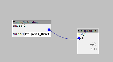
Apologies if this is straightforward but I'm struggling with something. I am messing about with the Axo and a breadboard just trying to learn the most basic electronics stuff. So far I can send a pot into Axo via an analog input pin and see the result from 0 - 64:
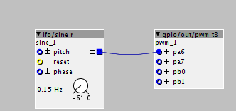
I can connect an LFO to a PWM output and see an LED dimming:
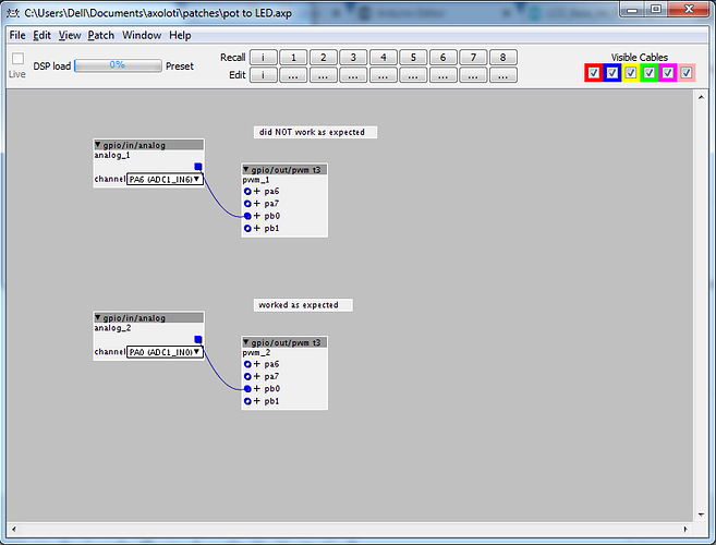
If I connect the pot directly to the LED (i.e. without going through the Axo) I can control the brightness. But... if I connect the analog input to the PWM output nothing happens and the dial "sticks" at a value of about 10:
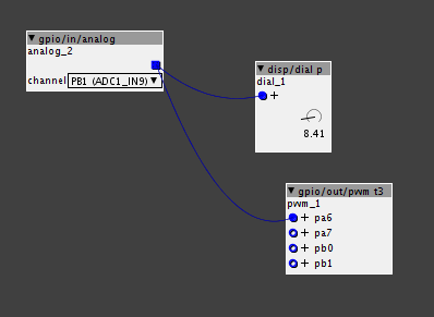
Why would this be?

#2

No-one? I might try on a different computer in case it's my Windows 7 machine causing more problems...

But would be useful to know if this was expected behaviour.


#3

I personally haven't tried it, but I would point out that PWM is a digital signal. ie- it's either 0 and Vcc but varies the duty cycle to give the ability to dim LEDs, control motor speed, etc. If you plug it into a analog input (ADC) you would expect to see either max or min- or whatever values correspond to 0 and Vcc- you wouldn't get a continuously variable voltage.

Possibly you could run the PWM output through a RC low pass filter and get a variable voltage that is measurable by the ADC. If you have a scope you should plug it in and take a look at the signals.


#4

I don't need a variable voltage though. I am trying to dim the LED by varying the duty cycle of the pulses. So, to confirm:

Potentiometer -> Axoloti (value between 0 and 64) : Works as expected
Axoloti (vale between 0 and 64) -> LED (varying duty cycle) : Works as expected
Potentiometer -> Axoloti (value between 0 and 64) -> LED (varying duty cycle) : DOESN'T work as expected

I will however try using an analog output instead of a digital output. It's just I was following this example:


#5

This is a wild guess, but what I would try if I were presented with these results —

You have your analog in on a pin that is also within the pwm group (see the available pin outputs on the object) — try changing the analog to a different pin not listed there and see if it helps.


#6

That's an interesting suggestion, will try that thanks.


#7

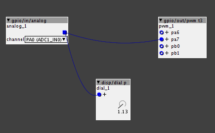
I am running this right now... it works as expected.
Pot is 10K linear


#8

that makes sense as even though pb1 is not connected, it is still "listening" as it is active in the patch object.
I have taken to stripping unused ports from my objects for this reason.

From the Init code:
pwmStart(&PWMD3, &pwmcfg);

palSetPadMode(GPIOA, 6, PAL_MODE_ALTERNATE(2));
palSetPadMode(GPIOA, 7, PAL_MODE_ALTERNATE(2));
palSetPadMode(GPIOB, 0, PAL_MODE_ALTERNATE(2));
palSetPadMode(GPIOB, 1, PAL_MODE_ALTERNATE(2));


#9

This was absolutely spot on.


#10

Great! Glad it worked out!