My rotary encoder on a single input


#1

I am all about the knob twiddling, but also about live playback of knob twiddling so although I am currently using pots I wanted to find a way to replace them with rotary encoders without losing extra pins.
I really am not an expert on circuits so I expect to be told its going to blow up any minute but it dawned on me that basically anything that needs multiple digital pins should be possible over a single analogue pin by dividing the voltage and reading that in software. Sooooo.......

I connected the rotary encoder so each pin gives a different analogue value, then decode that and feed it into a rotary encoder object, I figured out the analogue values by trial and error watching values change on my display.

Zero is the push button on the encoder, 32 and 64 are the two other pins, I set this by using 2k2 resistors.

I guess I need to do a circuit diagram to explain that, I will if anybody is interested.

The example above switches patches based on the value set by the rotary encoder.

Here is a video of switching between my 2 current patches :-

In case anybody actually makes use of this the files neeed to be compiled .bin files, they need to be in the root of the SD card and should be labeled with leading zeros, ie, patch000.bin, patch001.bin etc


Axoloti controller / enclosure / lopper synth
#2

Great - just in the middle of a controller box build, love to see your circuit diagram.


#3

Thinking about it there must be something wrong, the 64 value cannot be coming form the second pin, its too high. Perhaps its the inverse, the gaps between the signal where GPIO is not linked to GND at all.

In theory if they arent to be used at the same time I can add multiple encoders on a single pin. I expect to need debounce but so far so good.


#4

For completeness I should add for patch switching I then upload the above patch as the boot patch (start.bin) and then add the below to every patch, which basically exits and loads the boot patch to allow you to select a new one.


#5

superb! thanks kentronix,


#6

I'm interested to understand how you can accurately define backwards and forwards, because normally this is done by comparing the different states of 2 pins at the same time ?
The other solution could be to have one rotary encoder using 2 pins, then you can have a rotary switch lets say with 8 switch positions, this can be connected to an analog in using a resistor ladder for defining the position which could be say any one of 8 parameters, then you have the one rotary encoder to adjust you values. Or if you want to go further, replace the rotary switch with 2 push button, to scroll up or down through the parameters that you want to adjust.
:grin:


#7

You have a good point Gavin, after reading up on the encoders there should have to be a fourth voltage measurement for when both are high, which could be read and mixed in to both inputs on the object. I think the 64 value is actually the neither option so i am feeding in pin A, and Neither and its still working.

Certainly at the low speed I am using it at the moment for menu selection, perhaps its a lucky quirk of the object. I was thinking as I did this that if nobody else is doing it this way its probably wrong but then it just worked.

I am going to fiddle with the circuit to try to get a both voltage.


#8

So in theory this circuit should give an extra voltage for both pins together.

In case anybody is wondering I only have 2k2 resistors hence doubling up for pin B rather than just using a different value :grin:


#9

The recommended standard for resistors for analog inputs is 10K.

Having another look at an alternative option, no where near my axo to try out, but here might be an option.
- Connect Rot Enc as per normal, VCC, GND, Output A, Output B. I am ignoring the switch in this instance.
- With 3 x 10K resistors, connect all linked as follows..
GND -> 10K -> output A -> 10K -> output B -> 10K -> GPIO

With this, you will get no reading when both pins are low, when each pin is high, you should get a different reading. Not concerned when both are high, so ignore this.

The way to define the direction as follows..
You have a variable that carries a value that is reset every time both pins are low (variable = 0), if read value for A = high & B = Low, then variable = 1 (this is one direction), B = high & A = Low then variable 2 (this is the other direction).

So the goal here is to read the first state after both pins are low which is consistent in both directions to define the direction it is going in.

Well just a thought anyway...:grin:


#10

https://analog10.com/posts/rotary_encoder_analog_input.html

looks like something similar, using 3 resistors and a filtering capacitor


#11

Thank you mokomo !
It even shows me how to debounce :slight_smile:

Apart from the values and the cap this looks similar to the second circuit I posted. Wish I had seen that before :slight_smile:


#12

I'm guessing these values should also work fine with the axo? (axo works well with 10k to 100k pots i think)


#13

I would expect so yes, all pin possibilities will remain within 10-100k so it should be fine.


#14

A quick update, I replaced all the resistors with 10k and added a debounce capacitor, I also redid the patch to account for both pins at once.

New circuit :-

New patch :-

The new value of 26 is for both pins together, 32 is for pin A, 42 is for pin B and zero is for the button.
And here it is in 'action' :slight_smile:

As you can see its not quite perfect I am sure this could be improved with a bit more thought but its fine for my needs. Now I basically have a drop in replacement for pots in all my projects.


#15

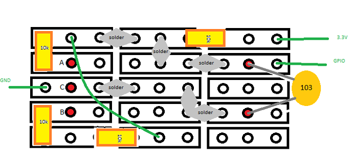
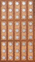
And here's my layman 'breakout board' sketch of your circuit using that sort of protoboard with lines of three hole copper strips

... green jumper wire, solder blobs, 4x SMD 10k resistors and 1 x 10nf capacitor. The red dots are the encoder legs poking through, with the encoder mounted on the rear..

(I find it works best with 43 instead of 42 in the second drj/math/== const i)