MAX11300 for CV-IN and CV-OUT


#21

I got the prototypingboard and managed to get it working on an arduino and this library
https://github.com/wolfgangfriedrich/Pixi_demo
Maybe a help for someone with better coding skills than me
Im trying to turn this into a script, but I'm not there yet.
Anyway, twenty 0-10V midi cc to cv outputs from the arduino 3.3V, will propabely require external power, I have only connected 2 pins at the same time yet.

Is there a somewhere I can read about SPI programming on the axoloti, I tried a couple of different posts on DACs and I think I mostly understand but this chip is a little not complicated since it needs to be configured as dac or adc or gpio in the setup


#22

any news about code? I got stocked at I2C code.
does max11300 have any input protection at its I/Os. perhaps user plugged in a signal source of 0/10V but input is configured to +/-5V volts?
the max11300 voltage capability is good for eurorack. most voltages should be around max 10Vpp and range as @toneburst wrote.

to prevent input damage or troubles with impedance I would recommend some multiplexing ICs logic, op amps, clipping diodes and rgb leds to display output mode at each jack.
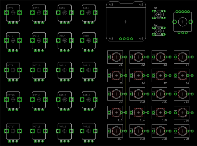
So a maple mini some pots or encoders, oled or tft display and some pushbuttons would be nice combination. a design like a korg ms-20, on the left side control parts and right side I/O patch bay. :heart_eyes:

If the euxo core is finished I would join a project to work out an useful I/O extension for axoloti.


#23

SPI_max11300_2-2.axp (24.5 KB)
I've made a script from the arduino pixi shield library and it works in pauls spa mcp4x22 patch, so here it is. The script contains all the register definitions from the arduino file to make it more understandable, i've taken the class-functions and turned them to regular functions.
The example uses two dac's (pin 0 and 1 and two adc's (pin 8 and 9). I've also done a 20 dac version, the remainder of that is commented out in the code. the 20 dac version for some reason only worked with 19 dac's in 10.0.9 but in 10.0.10 it worked great.


#24

@mnskll
thank you for the axo file. I played around with it a few hours and it works nicely. there some glicht on dac output and there is some noise while reading dac outputs with the config adc ports. did you also has those?
There should maybe a reset routine when max11300 starts. Sometimes the max11300 didn't start to work after activating live mode.

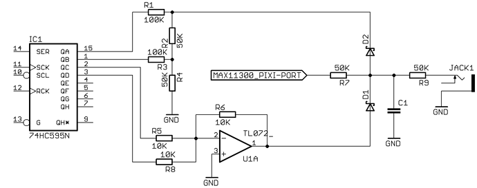
I did some thought about input protection and keeping flexibility. for most eurorack application a voltage range between 0V and 10V or +/-5V should be fine. selecting voltage range for I/O protection could be done manually with some DPDT switches:

or with digital control (595 supply = 5V and it needs a level shifter for spi):

some duo leds (red/green) controlled by 74x595 could display the I/O state or an cheap oled display, encoder and some buttons.


#25

That look s very cool @paul :slight_smile:
Could the i/o's be software configured to be either inputs or outputs at runtime, or would it be fixed as 10 in, 10 out?

a|x


#26

@toneburst yes, there could be easily an object with 20 I/Os and some drop down menus to select function with @mnskll code.


#27

led's for showing if the ports are configured as in- or out-ports is naturally a great idea,but for the moment I'm keeping it simpler, just testing. I got some noise on the inputs, but I made very simple connections so I blame those so far.
the script is for controlsignals but i also tested note-cv out and it seems stable. I just tested by ear but it seemed to give 1V/oct across many octaves (0-10V, thats 10 octaves) but I haven't used any instrument for measurement, just an analog synth, but it sounded in tune across the scales at least six octaves, hard to tell further than that
I just used the 3.3v input, no external power, but I suppose that one needs external power for all channels to function reliably.
input protection is probably a very good idea, but it's a bit tricky, you propabely don't want to leave the switch in the wrong direction, but it is an easy mistake to make, maybe there should be a led telling witch range is set in the code, or a digital switch that automatically switches range if it is switched in code (now it's getting complicated) or maybe easier to have a way of telling the axolotl witch way the switch is set (maybe a 3pdt switch) and then automatically set the range in the patch

edit: ok now I see, you have digital control, but I don't really understand the circuit, how do you get the +10V? the negative side with the inverting opamp I understand, but doesn't the positive side just give you +5V? (my electronics skills aren't that great though)


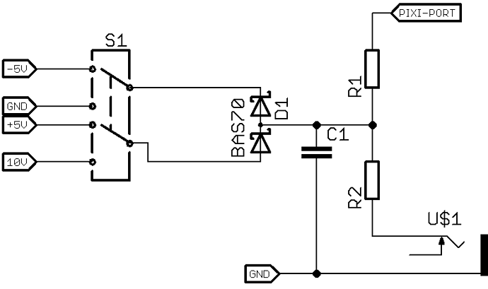
#28

you're right with getting things simple at the beginning. I was only thinking about a method to check max11300 mode state. I think this will be importing when using this variety of functions.

1V/oct tracking should be stable with 12bit resolution and a 0-5V range. I'm working on 1V/oct calibration for the euxo. so this could be easy used with the max11300 IC.

your right, my second circuit don't work to get the +10V. So there has to also some amping op amp. This would drop part cost very high… an other solution would be some 4016 analog switch IC where you can digital control the voltage limitation.
The old school way with a three position switch would be the cheapest way to go.


#29

hey did you guys ever finish your work on this?

would this be a suitable board for direct connection to axoloti?

Mouser.com MAX11300 board


#30

Guys, i tested this very successfully, my oscilloscope shows proper voltages from the max11300 outputs without any hassle on setup.

but it seems the conversion frequency is pretty low, around 800Hz currently. anybody knows a way to get these smoother? according to the datasheet the chip can transfer up to 400k samples per second, up to 10k on the ADCs. how do i get closer to those numbers? even if i divde by all 20 I/O of the chip i should get in the 10-20 k range, not under 1k.... is it maybe an issue on the axoloti side? how often/how are the "script" axo objects that @mnskll uses for this driver? thanks btw, if you ever pass througgh again: you're the man. so, could i maybe try migrating said script into an axo object in the s-rate section? to get higher data transfer/DAC update rates?

edit. i am so happy. instant super convenient eurorack CV control. 20 channels. i really have no clue why nobody is just making a cool crowdfunding dollar with a streamlined version of a 11300 axo. on a second thought, axoloti availability would probably ruin this endeavour currently...


#32

Hi @weasel79, glad you found the code useful.

Personally I sadly haven't used the max11300 for anything useful yet, too many projects, too little time, but maybe now is the time to pick it up again, thanks for the reminder. :slight_smile:

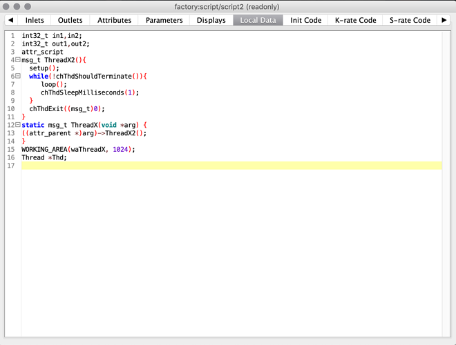
It was a while ago I did this, and the code was borrowed from other people, from an arduino script originally, so I really don't remember every detail, but I poked around in the axoloti-object and found there is a 1 millisecond delay in the looping code that may explain the 800 Hz. I don't remember if I tested without the delay or if I just put it there because there was a similar delay in the arduino code, and I thought it was needed.
The while-loop calls the "loop()" function, witch is inherited from arduino, where it loops, but here, in axoloti, it needs to be called repeatedly to loop. (I don't remember if I wrote his or if I borrowed it from someone, it was three years ago).
After the call to "loop()" there is a "chThdSleepMilliseconds(1)". Comment out that line and see what happens, I can't try it myself since I'm away on holiday and my axoloti's back home.
Let me know if it works
mnskll


#33

yeah thanks man i saw those lines in there, was assuming they are to keep the spi timing but since it's timed SPI anyways that shouldn't be needed maybe right? will investigate tomorrow night. also i'll update with some more measurements on voltages, timing etc

and yes i absolutely agree now is the time for you to pick it up again!
for you too @tele_player lol or was that just another negative rant you deleted?


#34

Not negative.

Just wondering, about voltages applied to MAX chip, and ranges on inputs and outputs.


#35

Yeah inputs would definately need some kind of overload protection circuit for a public product.
Input and output ranges are conveniently configurable per pin via SPI, 0 to 5v, 0 to 10v or -5 to +5v. People tested it to be precise enough for 1V/Oct, quick maths say 12bits give you about 33 steps per semitone, 1.5ct.

On the power supply side you might want to use the external power pins on the max board instead of the axo power i am currently using. To make sure you have stablte voltages, best operation and enough amperes.


#36

I was interested to hear how you powered the chip, and what output voltages you got.


#37

For the first trials i was using the axo 3.3v pins and still measured 10Vpp on the 2 output pins i tested. Axo itself on USB power. Will hopefully have some better test results tonight. But i assume for 20 pins of eurorack i/o you definately want to use a reggulated external power supply for the max chip. ie. the eurorack power rails...


#38

Now I see, you used the evaluation board, which provides the DC-DC converter.


#39

Oh yeah for sure, same small dev board posted above. I definately was not gonna build my own circuit. which of course would make sense if someone was to make this a comemrcially available axoloti-shield.


#40

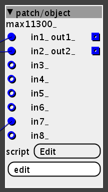
Sooo. How do i go about converting this driver script to an axoloti object? how to realize the functions? i guess the setup and loop parts can go in init code / k-rate code, but i am assuming to gget the functions working gi have to do that external include prorgamming thing? any hints here? or is there a way to add more inlets/outlets to a script object?

edit. i realized i can just edit the script.axo into a scriptx8.axo but UUID and SHA giving me trouble. so yeah if someone has an idea how to convert this driver script to objects, i'd be very thankful. as will be the thousands of eurorack users who will come flock to axoloti once this works.
edit 500: ohh nevermind i'm stupid. i confused the little "edit" button on the scrip object with the actual "embedded obcejt edit" button which wasn't there. should be no issue now. also by now i read up how to properly make a new object in the editor...

edit. the slow update rate i mentioned earlier probably has to do with the driver scripts being called at k-rate only? i currently have a perceived DAC sample rate of around 500Hz lol. not really enough for even a LFO. max11300 can do 400kHz SPI as per datasheet... on my oscilloscope i can see the rasterized steps moving slowly up and down and also slight binary variation in the step length/sample time. which i think speaks for the somewhat low-resolution k-rate LFO being gout of sync with the SPI cycles and the script object... will try make some videos tmrw. @mnskll i just now understood the Local Data calls of the script functions, will try removing that thd delay tmrw..
maybe it needs to be a "script2" object?

edit 6. very happy to report that i currently have 8x CV/Gate I/O controlled by the max chip in axoloti. was pretty easy after all and i think with the help of all you guys reading this it should also be easy to take it to the finish line: convert to a proper driver object and possibly inlet/outlet/config objects? or however you go about that. and then i think it should be done at s-rate if possible. overall i keep having thoughts k-rate should be a little faster, even at lets say 20Hz a 3k rate gives you a quite grated step-sine?


#41

As @mnskll wrote above, the limitation on rate that you notice is most likely caused by the 1ms delay every time the script object runs.

As for whether k-rate is too slow to produce a smooth output, you need to think in terms of basic sampling concepts, and recognize that steps in DAC output should be handled by an appropriate low pass reconstruction filter.

Also worth considering, if you try to send audio to these DACs one sample at a time, jitter might become an issue.