Is it possible to make a 3 phase VCO or MIDI controlled oscillator?


#1

I was going to buy an axoloti to make a 3 phase oscillator, but I would like to check first if it is possible. Can multiple sine wave oscillators be synced together at different phases?

I will be using the output to make a 3 phase motor spin at musical frequencies.

Thank you for your advice.


#2

Generating three sine waves 120 degrees apart is not a problem, but there are only 2 audio output channels. Using an audio output to driver a motor is not the common approach, H-bridge drivers are chosen for their energy efficiency. Driving a three phase motor is a pretty specific application, disciplining a motor to track pitch changes quickly and over a wide frequency range is not easy. I'd suggest to develop this application using a three phase motor controller evaluation kit.


#3

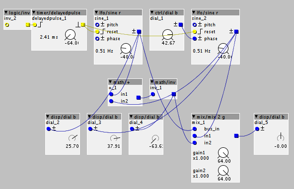
Just something to note, if you output two sine waves one at '0' degrees and one 120 degrees behind, it's possble to derive the 240 degree one from the first two, so you don't actually need 3 outputs.

EDIT: Here's a picture demonstrating how to calculate the 240 degree signal.

You add the 0 and 120 degree signals together (which gives a 60 degree signal). That inverted gives a 240 degree signal. So what I'm suggesting is that you do this in the analogue domain, you could do it with an opamp. Obviously then you need some kind of driver circuitry.


#4

SirPrimalform

Thank you. It will be easy for me to generate the 240 degree signal with opamps. Can you show me an image of how to make just the 0 degree and 120 degree signals from midi note in.

I have just ordered an Axoloti. Very excited.


#5

Johannes

I will work within the limits of the motors capability. I am not expecting instantaneous acceleration, or to go be able to go past 400Hz.

3 phase motors are fairly widely used. They are often called brushless motors. Even brushless DC motors usually use 3 phase internally, and are hackable to run off 3 phase externally.

I will wait and see how well it works, maybe I am being overly optimistic, but I am assuming the motor will be forced to lock to the Frequency of the rotating magnetic field created by the 3 phase current.


#6

That's a bit trickier without writing a custom object (or at least modifying existing ones). None of the audio rate sine oscillators have a phase reset input, which is necessary for synchronising them. It is however theoretically possible to cause a specific amount of phase shift using a filter with 1:1 pitch tracking. Still, that seems a silly way to do it in a digital system - someone may even have already made a sine oscillator phase control and reset inputs.

Hang on a moment, it should just be possible using one phasor and the appropriate offsets. I'll try and whip up an example in the editor. Meanwhile, I'm really curious as to what you're planning to drive with the musically tuned motor? I find electromechanical instruments particularly fascinating and have had a few ideas relating to driving motors at musical pitches myself (although I got stuck on the idea of using a stepper motor, using a 3-phase motor makes much more sense).


#7

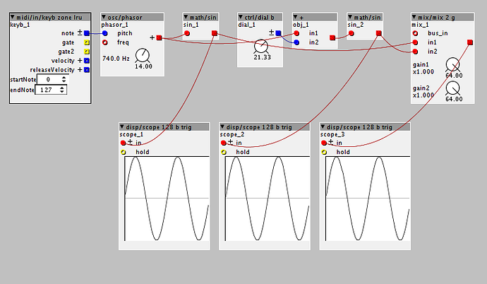
Here you go.

The phasor is outputting an ascending saw from 0 to 64, this corresponds to 0 to 360 degrees as far as the sine function is concerned. By sending it simultaneously into two sine functions - one with an offset - we obtain two sine waves with the appropriate phase difference. Since 0 to 64 corresponds to 0 to 360 and we want a 120 degree difference, we add 1/3 of 64 as an offset so that the second sine function is seeing 120 to 480 degrees on its input. Again, it would just be a question of sending both of those to the left and right outputs and using analogue electronics to derive the third.

By the way, that + object I'm using to add the object is actually a simple subpatch I made because there is no red+blue=red object normally. With stock objects you'd just need a blue to red converter and a red+red=red object.


#8

Thank you, I will give it I go.

How come your 3 scope images look the same?

The boundaries between a 3 phase motor and a stepper motor are blurred especially when you realise that a stepper motor is ideally driven by sine waves.

I will be using it to make and optical tone wheel, similar to a Hammond organ.


#9

Because the scopes are synchronised to zero crossings. You can't see the phase difference because each scope is synchronising to its own input.

That actually gave me an idea, a scope with a separate trigger input would be really useful. That way I could connect all the trigger inputs to the same signal and then connect the actual trace inputs to different signals. That way the phase difference would be visible. @johannes Does that sound hard to do? It seems to me that it just requires the trigger reading code to be connected to a separate inlet instead of reading from the main input.


#10

Sounds like a good idea. So I take it that users can just code new objects for this software.

I am not good at coding that is why this project appeals to me. I can't give advice on hacking the code.


#11

Yeah, it's very user extensible but I have yet to actually code any new objects myself. I think the scope mod I was proposing is probably quite easy though, I might try it myself.


#13

I say, what a small internet it is. It turns out we have crossed paths before!
I know your website already, although I didn't recognise it from it's URL, that string resonator is unmistakeable.
In fact, it would seem I left some comments on your site back in 2008 as, although the comments seem to be gone now, I have an email from you replying to the comment. I came across your site while researching a similar idea inspired by the Incredible String Band's voice sitar. I never did get anywhere towards actually making it, but hey.


#14

A separate trigger inlet on scopes would indeed be useful and not very hard to do. Another way to observe the phase difference is using non-triggered (free running) scope objects, and connecting their freeze input together

A bit further thinking - yes two outputs is enough for three phases, and if the three phase motor coils are connected in a triangle configuration, the third terminal can just be the mid voltage (the other terminals swing around mid voltage). Actually triangle configuration is not even a requirement, star configuration is also possible, just leaving the center floating. For better balance the third terminal to mid voltage should have a similar impedance as the drivers to the other terminals.
Then you "just" need appropriate amplification for the audio outputs. Those requirements depends a lot on the sort of motor you intend to drive. Be careful that generative behavior of the motor does not damage the amplifier.


Phase inversion on audio signal
#16

I sent you a PM here on the board a few days ago.