Hi all, just got my new Axoloti, as topic, has anyone tried anyway to do so? thanks.
Is is possible to have analog outputs (+/-5V)?
In its current basic form and firmware etc, no. But I guess it depends on what you are trying to do ? It has PWM's, you can interface with other microcontrollers etc..
Thanks  but at least I need 5 analog outputs with 3.3V, I only see 2 in the patch? (PA4, PA5)
I wanna use it for my laser CV control, i send analog signals directory to my galvanometers, the sample rate is related to the laser graphic resolution.
but still so excited to have my first board!
It depends how "analog" you want them to be. I guess that PWM would work, in which case you can have more than 10 outputs giving you continuous values from 0 to 3.3 V. You'll need to filter the PWM signal so that it fits your downstream application.
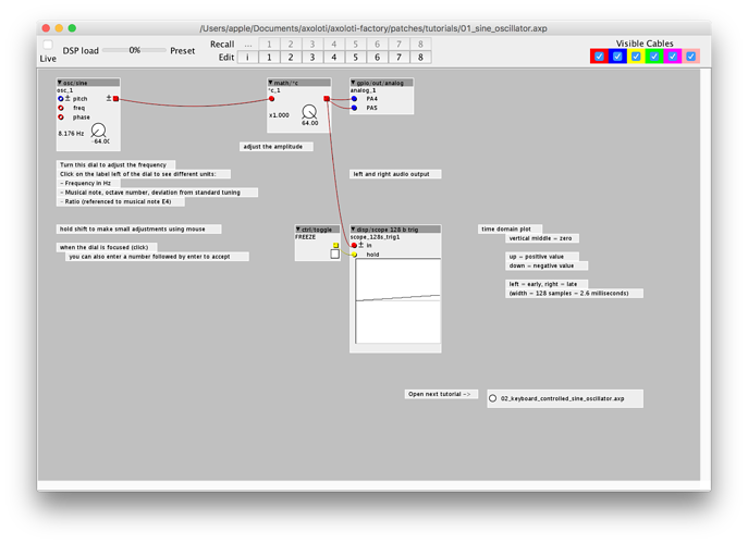
Check the GPIO outputs there:
Thanks Charles, I expected analog DC coupling outputs, the sample rates affects my laser graphic quality. (by my understanding PWM gives you ladder shape wave form according to sample rate?)
but I guess I have to accept only two outputs now...
PWM gives you a square wave, with an adjustable duty cycle. With an Arduino Uno, it's the only way to get a "kind-of-analog" output, it looks like this:
http://www.arduino.cc/en/Tutorial/PWM
With axoloti, the "on" value is 3.3V (not 5V), and the PWM frequency is currently fixed at 97.65Hz.
You could filter the PWM output to try to get "only" the DC component, i.e. the average value, using additional electronic circuitry.
on the off chance that your laser is TTL, the 3.3v digital outputs would work fine for RGB, then you could scale the analog outputs to 5v for x and y. I have a TTL laser and that's how I'm planning to implement.
As long as you add an appropriately designed reconstruction filter, the PWM outputs will be an analogue. Their steppiness depends on their bit depth, but that's a problem on all DACs.
thanks for the answer, then which object in Axoloti to make a constant +/- 3.3V audio output like [sig~] object in max? I only get 1.6-1.7 readings from PA4 and PA5, is that correct? and I need negative voltage too....
IIRC the patcher objects work at -64 to 63 when the total range is -128 to 127 so you can add oscilators together without clipping. Try sending the output through both inputs of math/+.
Hi Ott, thanks for the reply, can you screenshot the way you refer to make a constant value? I am not sure if I get it.
and if you say I can only adjust it between -64 to 63, does that mean I can't generate a 0.00001hz sin wave or a constant value to PA4?
we are working on it....
a lot of digital talk her. but we need to go into the analog world now.
adding a capacitor will already lead to a symetric sygnal and we then amplify it to our range we want to.
maybe some decent filtering stage would be useful.
more to come soon...
m

