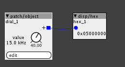
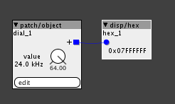
about the 'code comment'
the 0x50000000, confuses me a bit... as in the freq dials 0x07FFFFFF = 24kHz (which is max we can expect)
so I'm guessing it might mean 0x05000000, which is 15kHz ..
@johannes simple typo? are the filters only 'stable' to 15kHz, so little gain in a freq variation?
How to set-up 20Hz to 20kHz range on the filter dials?
Haven't tested my hearing in a while, but when I were a teenager, I was probably too neive to appreciate the ability. And now that I'm old enough to appreciate it, I probably don't have it
That said, I do know a cool place where Goths hang out, so maybe I can borrow a bat or two!
Can't find the cable so did a bit of hardware jiggling instead.
The filter is passing frequencies up to 24kHz. I passed uniform noise through the filter wide-open, then fed it into Audacity and checked the spectrum. It's definitely passing audio up to 24kHz.
While I was at it, I also checked my hearing and was shocked to find I can still hear 20kHz. I'm absolutely amazed because last time I tested, I couldn't quite reach that, but who knows, maybe it was my headphones!
I'm feeling quite pleased with myself, you can call me 'Golden Ears' if you like
Cool, is itpossible for you to determine if there are any 'artifacts' above a certain frequency.
I need to determine the benefits before I go thru the effort of creating various filter variations.
( it's not hard to do, but will take some time, so it has to be right)
There was a notable (but very tight) spike at around 23kHz, but I never mentioned it due to being above the audible range, and because I had to use a basic soundcard to do the reading anyway.
I did test it using various sample rates, just in case, but the spike was persistent.
I should stress though, it might not be due to the filter, it could just as easily be interference due to the everyday quality of the soundcard. I've come to realise it isn't even as capable as the souncard in my older machine in some respects. Trouble is my other machine is effectively out of service while playing around setting up Linux on it. I'm trying to get stuff set up cause it used to have Windows XP on it, but it's a Linux box now.
BTW, Mark, I'm curious why there's no Band Reject filter, is there a specific reason for it?
If there isn't then please consider this a request for one if possible. I started to make an equalizer again and realised there's no Band Reject filter!
Try a notch filter.
Another option is, if I remember correctly, to use a bandpass filter and then invert it. I think I used that method when I worked on an EQ long time ago.
When using a bandpass filter, when the signal is not inverted the bandpass filter boosts the signal at the specific frequency... And when inverted the BP filter subtracts.. A bit like Pultech style Eq, you have to select to either boost or subtract
Thanks, but I already tried that and it wouldn't work. You do mean for me to use the invert object on the output of the filter, right?
Directly or do you mean something else? I even tested the invert on a bipolar display dial just to make sure it was doing it's thing, and it was fine.
Any idea what I'm doing wrong, jaffasplaffa? anyone?
Shoudn't I be getting an inverted peak from the bandpass filter if I put the math invert object directly on the output of the filter?
I'm not 100% sure whether it should do that, or whether it's a bug.
Yes put the inverter directly on the filter. Anyway here is where I landed. Nothing special and not that good actually. ANd I never really used it, cause I didnt think it was good enough.
You should use an analyzer to see the effect. And actually I think there is supposed to be an allpass filter in there somewhere in the signal path.
But I think @SirSickSik has been working on an EQ. I don't know if he put it in the community library yet, but I saw a picture of it on his contributors page And there is also an eq in the factory library.
Eq1.axp (4.3 KB)
@jaffasplaffa
Thanks for that, and no wonder it wouldn't work, it was the stuff that followed the invert I got wrong. I had to remove that object you were feeding into the filter's pitch though, it was highlighted in red and refused to run unless I removed it. Got it working though, and learnt something from it
@SirSickSik
Hey Remco, your ParaEQ was one of the first custom objects I tried (probably the first actually). I tried it and didn't understand the way it's set up, so intended to get back to it. I just checked it out again, but I'm confused as to whether it's designed to be run in parallel with other instances, or used on it's own.
I'll figure it out, but I have to say, I don't think I've come across an EQ object yet that would work as I imagine/want it to work. I just want to build a Parametric EQ with a total of five bands, so that:
- Each band can be set anywhere in the 20Hz to 20kHz audio range.
- Each band has cut and boost using a bipolar control.
- Each band has resonance control.
- Band 1 can be switched to low-shelf mode if required.
- Band 5 can be switched to high-shelf mode if required.
That's my ideal equalizer, and I've been trying to create it using the factory objects so that I know exactly what it's doing and how it's actually working. I read your thread often and drool over what you do there, throuble is, because it's code and not an Axoloti patch, I can't see what's going-on inside the things
First of all set the amount of stages you want to have (how many filters it includes)-> so in your case, you set the "stages" attribute to 5.
The "stage" control lets you select which of these stages you're about to edit.
When changing stage, it automatically loads the settings of that stage.
STorMS->can be used when you want a mid/side spreading mode when using two modules for left&right signal path, the gain-controls will be inverted for the module that has this control "on". To share settings, first setup the settings in one module, then load these settings into the other (save to a preset number and load same preset number on other module) and set the "STorMS" of one of the two modules to "on".
the mode of each filter stage can be set with the "mode" control.
0=off/thru
1=peak
2=lowshelf
3=highshelf
so in your case the different modes for 5 stages would be:
2,1,1,1,3.
the cutoff band and gain of each stage can be set using the freq/reso/gain controls, of which the settings of the stage will be loaded when you change the "stage" control.
for "modders":
the settings are saved internally in an array.
as in:
array[stage*4]=param_mode;
array[stage*4+1]=param_freq;
array[stage*4+2]=param_reso;
array[stage*4+3]=param_gain;
This array could be updated from an external module and modulated. First add a "objref" attribute and give it a name, eg "setting". Then add a frequency inlet to your module and a "stage" parameter.
As code you can update this array like (eg for frequency)
attr_setting.array[param_stage*4+1]=inlet_freq;
This module then allows you to modulated the frequency.
Of course, also an extra control (0,1,2,3) can be added to allow you to choose which setting you want to control. Mode=0,freq=1,band=2,gain=3
then it would look like this:
attr_setting.array[param_stage*4+param_parameter]=inlet_freq;
Thanks Remco, been at your ParaEQ almost all day, the explanation was clear and understood.
Gotta be brutally honest though, it really doesn't do what I'm expection it to do, and actually, it's way more sophisticated than I need which might be part of the problem. I don't know why, but all of the EQ's I try seem very weak. I don't know if it's just an accepted way of designing them among the coders of the forum, but there's something lacking somewhere for some reason.
No matter what I try, whether I patch something up myself, or use a ready made EQ such as yours, I feel like I'm twiddling knobs and it's just not doing what it's supposed to do, and even when it does, there's barely anything happening, no satisfaction.
Let me explain a set of ideal objects to you then maybe you'll see what I'm getting at.
Three independent objects:
- LP filter with cutoff, resonance, and bipolar gain.
- BP filter with cutoff, resonance, and bipolar gain.
- HP filter with cutoff, resonance, and bipolar gain.
- Each filter type has an inlet for cutoff, resonance, and bipolar gain.
- No toggle on any of the filters, because a bipolar dial should be capable of positive and negative gain.
Those three independent EQ objects would allow the construction of a complete EQ quite easily, no matter what the configuration. And because each object in the set is not a complete EQ on it's own, it's possible to pick and choose which one is needed when using them in other situations where only one stage is required.
I feel like such a set of objects is the only way I'm ever going to get the type of EQ I want out of Axoloti, so if you're looking to add more objects to your contribution thread, please, it would be very cool to have that set of objects exactly as specified, nothing more, nothing less, no presets or any other functions whatsoever.
Basically, just purpose-built, independent EQ stages with inlets
Hey there, I need fullrange HP and LP filters for a performance next week. Is there any news on this?
I tried the one from @thetechnobear technobear and it seems to cut even more than 13hz even when fully open.
bump! 1,5 years later and still no full range filters? Did anyone here make one??
The big problem here is that I usually have on/off knobs for the filters and a lp filter set to 13k makes some coloration at 13k that is very audible. This thing is driving me crazy! I expect a Lp turned fully up to be more neutral.
@thetechnobear I tested this one and it audibly cuts even more than the 13k of the current filters..
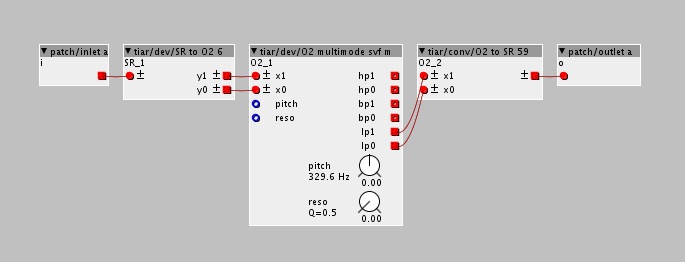
One of the filters that I find having the highest frequency range is "tiar/dev/O2 multimode svf m", from @SmashedTransistors.
If you want to get to the bottom of which filter has the best range, or just sounds the best, make a patch and load every single filter up in that patch and then compare them. I have done that a few times and found my favourites. The above mentioned filter is one of them. You need to use a couple of extra objects for the up/down sampling. It sound open and nice, but it uses 11% dsp, though.
I already made a filter shootout and all of them coloured to much. I didnt test this one from tiar because I assumed its the library multimode in stereo.
What do you mean by etra objects for up/down sampling?
Those are actually inlets for upsampling and outlets for downsampling.
Set it up like this: