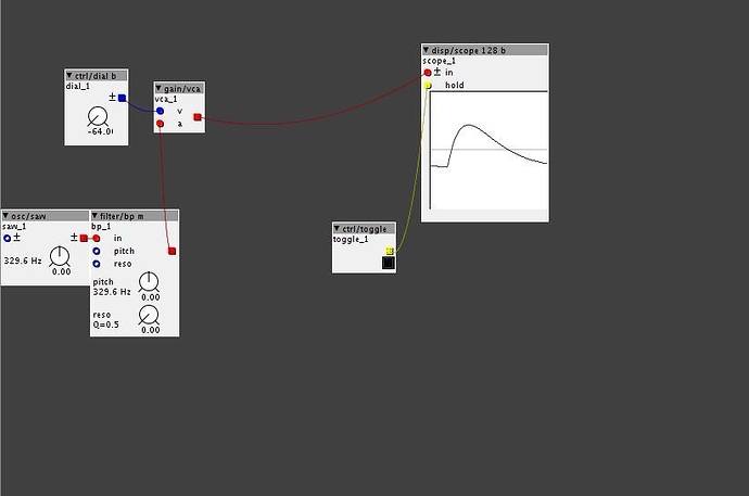
I think if you take a array of band pass filters in parallel, and give each an input into a mixer, you would essentially have a resonant parametric EQ, as you'd have adjustable frequency range, and bandwidth(via the mixer), as well as resonance. Could be interesting.
How to build an equalizer?
hmm technically an EQ should be able to boost a frequency too, so maybe have a VCA for each filter instead of a mixer, and a constant knob to adjust the VCA's amplitude, and then use adders to mix the signals together.
Hey mate  Ups forgot about this post
Nice to find an example. I will definatly loo at it. THANKS mate 
Ok have been playing around with it for a little while and it has got some potential, but I am not sure what actually happens when the dial b that is feed into the vca goes in minus. Something happens, but I am not sure it is subtracting as supposed. Need to dig out an analyzer to check. Also it consumes around 8 percent og Axoloti DSP. That is a lot. We need to figure out how to make ot more efficient too.
Anyway, I added on/off button + mix function. Mix functions seems to be a good idea, though some aliasing seems to occur, but it sounds deeper and more fat than without mix Maybe adding HP & LP as two of the band would be a good idead too. Going to try that
Equalizer1.axs (7.7 KB)
A notch filter would be nice for this. Then you could just use bp if you want to boost and notch if you want to subtract. As far as I now this is also the technic used for building the Manley Massive Passive Equalizer; you select either boost or cut from a switch. I can live with that, but for this, the notch filter is needed. Unless there is a way to "invert" the bandpass filter so it cuts instead of boosts. But i dunno if it is possible.
http://www.uaudio.com/store/equalizers/manley-massive-passive.html
when a negative "voltage" is applied to the VCA, it produces negative gain. This to my experience inverts the wave form
IHmm, I am not sure. When I listen to it(and look at Axoloti analyzer) it doesnt sound like a notch filter(or band reject actually), which essential is the opposite of a bandpass filter.
Need to do more testing 
Here is an awful illustration of how I am pretty sure they react  And how it sounds like....
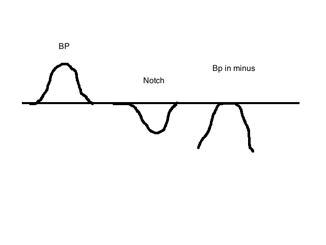
that would imply a negative offset is being applied, if you go into objects/disp and use the audio rate 128b scope, you'll see that when you apply negative "cv" to the vca it actually just inverts the signal. attenuation occurs between 0 and positive, and negative and 0, however above or below 0 technically produces positive and negative gain respectively For instance here i have a saw wave osc through the bandpass which is set to center, or basically all the way open so that it has little to no effect on the actual wave form. 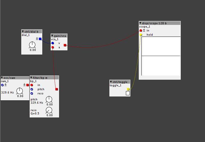 Here we have the bipolar Dial set to 0, no signal gets through, creating absolute attenuation.
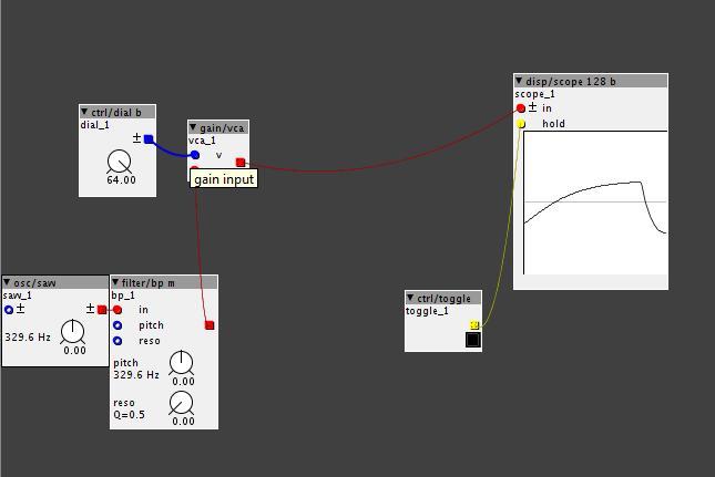 Hear, we have the dial set to +64, causing the wave form to be passed through the VCA with full amplitude, and no inversion.
Here as you can see is the interesting part, the VCA has negative gain applied to the wave form, causing it to be inverted. Its troughs are now peaks, and its peaks are now troughs.
I also use the spectral/analyzer 24.
Sorry those picture does not say anything about how the bandpass filter affects an audio signal. it show the PHASE of the signal... which is non related to what we are trying to do.... SOrry I brought up the "invert" word. I only used it to describe the notch/band reject filter. It is not really the right word to describe it... BUT a bandpass adds and a notch/band reject filter does the opposite, subtract... and has nothing to do with PHASE.
If you want to see how it really affects the signal use this: spectral/analyzer 24.
About picture 3: it is not subtracting.. Yes it might be subtracting, but not like and eq would do.... THis is how any digital parametric eq would look like: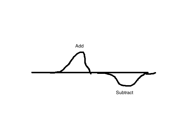
And that pciture cannot be compared to anything you see in the scope... THink of it more like how any digital eq looks... This is what a bandpass and band reject looks like..
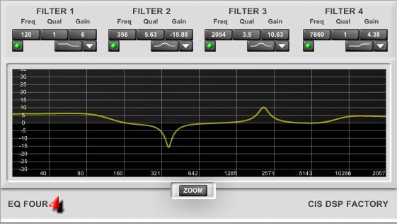
ahh ok, i thought you were talking about the effect of the VCA on the signal for some reason.
I was in some way.... But look at my kindergarden style drawings again  When you move the vca to minus it does not do subtraction.. It probably changes the phase like you say.. SOmething happens but I am not sure what........ But that is not what we are trying to do.... When boosting we want it to look like the "add" curve and when subtracting we want it to look like the "subtract" curve. And setting the vca in minus does not do that. For that we will need a notch/band reject filter....
Im afraid i dont know enough about EQ's or filters to implement a thing with a gain like that, i will experiment though and see if i can come up with anything.
Well we can boost/add... but not subtract....yet 
I just googled inverted bandpass filter and found this. An inverted bandpass filter is a band reject filter... BUt I just dont think it is a easy as adding an inverter after the filter... anyway going to try now...
Will read this later tonight:
http://www.bu.edu/eng/courses/ek307/documents/ActiveFilterNotes.pdf
I think ive got it this time, this one allows you to cut or boost specific frequencies, pick which frequencies to cut or boost, and adjust there amplitude, as well as the "bandwidth" i think. Check it out and let me know what you think, and definitely improve it wherever you can!Equalizer.axs (10.5 KB)
It is very cpu intensive, but i think if you paired it down to just single "bands" it would be a bit easier. It doesnt necessarily have to be a four band, since its just four identical circuits repeated and fed into a 4 channel mixer.
Each frequency has a dial that controlls whether it is "cut" or Boost" turning ti all the way left, will boost it, all the way right, will cut it. you can controll the depth of the cut with "bandwidth" and also selectively amplify or cut the overall effect via the mixer part.
2BandEqualizer6db.axs (5.8 KB)
I made this one too, which is only a two band, High and Low, and in a more traditional 6db/oct filter range(1 pole). It uses only 8% cpu usage, which is still a lot, but is much less then the 4 band one.
Also, this one specifically uses a highpass filter, and low pass filter.
Thanks mate  will look into it
  I am very curious of how you managed to get the cut bands
it was actually fairly simple once i figured it out. I think you'll find it humorous somewhat.
Just wanted to note that I added a parametric equalizer object to the community library:
jho/filter/para.axo. You can cascade them to get a multiband equalizer.
Parametric-Equalizer
Thanks @Jan 
I have also made a bandpass/band reject filter, using allpass filters, that works pretty well. But I look forward to check this one out too. It is made in 1.08, right?
Yes, for 1.08. I think the existing filters (including yours) sound really good. But I need an eq for surgical correction for the pickup-sound of my accoustic guitar. Until now I used the analog ParaEq from Empress.

