Help advise a total and complete beginner on how to build my enclosure!

controllers
midi

#1

Warning: this post is long and is written by an incredibly ambitious and clueless person.

A few weeks ago, I made a preliminary post asking about the enclosure I wanted to build, in order to make sure that it was realistic. Luckily, the good people of this community informed me that it was. Since the post, my Axoloti Core has arrived in the mail and I need to stop playing with it for 2 seconds so I can build an enclosure for the thing! There's no real rush, apart from my excitement to materialize this idea.

So, for the build

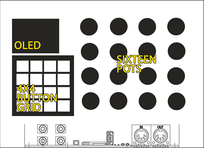
This is a very rough sketch of the general idea. By rough, I mean I found the axo schematic somewhere on this site and pasted it into photoshop, eyeballing the size. Not a final product. The faceplate will be 8.25" x 6" (need to get more familiar with the metric system before I start using the Synth Panels Designer extension!) The enclosure will be inside of a prebuilt box, so the size of the faceplate is fixed. The Axoloti will be visible out the front, but only the in/outputs will be visible.

I tried to correctly place the dimensions of the OLED w/breakout board, as well as the 4x4 button grid correct to Adafruit's specs. As for the pots, I could't find the size of pots anywhere, so each one is inside a 1"x 1" square while the actual circle sizes are completely arbitrary. The knobs will probably be much thinner.

Now for the parts I need help with.

I'm a beginner to electronics. I've used a soldering iron before, but consider this the project I'm "beginning" electronics with. In my previous post, I was informed that I might want to get a multiplexer, while someone else suggested I get a Teensy 4.1 which would do the job a multiplexer would and transmit the signal from analog to midi. I've decided to go with the Teensy. Other than 'it sends midi signals and connects via usb', I haven't got a clue how a Teensy works.

The following questions will illustrate that I need help with basically everything, but I understand that answering answering all these questions might take you forever, so I'm willing to consume any material (video, books) that will answer these questions also. Please just point me where to go!

The questions (imagine that I don't even know if I'm asking the questions properly):

  • How do I connect a Teensy to an Axoloti?
  • Do I need anything, aside from wires, between the Teensy and the Axoloti?
  • Will I be using resistors, capacitors, or additional electronic components for this project?
  • How does the Axoloti know that it's receiving midi signals instead of analog?
  • Is the teensy capable of handling all 16 knobs as well as the button grid, button grid LEDs, and the OLED, or should I be using the in/out pins (is that even the right terminology?) on the axoloti, or do I need an additional board to make all these connections?
  • Can I mount the pots straight to an aluminum faceplate with the nut/is there anything I need to know about that?
  • How to wire pots together.
  • Actually, how to wire everything together.
  • Something about 3.3 volts that sounded important (yes, it's very important, please tell me about this)
  • Can I use the OLED as an oscilloscope without any additional hardware?

Bonus question:
- I found 2 Adafruit 12x16 bit PWM boards on the ground out of nowhere, can I use these somehow? I know that PWM is used on analog synths, and that the Axoloti is digital so it won't do me any good there, but I don't know any more than that!

My current shopping list (please add if I need anything)
- At least 2 breadboards for testing
- 16 pots (I have the knobs)
- A whole bunch of wire (are there different types of wire I should be using?)
- 128x64 OLED display
- 4x4 silicone button pad, LEDs for it, board with buttons that goes under the pad.
- Teensy board (how do I connect it to Axoloti?)

Please feel free to tell me anything I'm missing, and if I've left it out of the questions/list, assume that I don't know that it exists. I'm not worrying about programming the OLED for now, it appears that there are plenty of resources on this forum for that.

If you've made it this far, thanks so much for your time! Doubly so if you're answering any of the questions. I'm excited for this project, and I'm hoping to make a video afterwards to show everyone here, as well as my friends to blow their mind about the Axoloti.

#2

Why use a teensy board, What you want can be achieved with the axoloti itself, with help of 2 MCP3208's (A/D converter for the pots via SPI) and perhaps some MCP23017's (via I2C)....

Nice layout btw!


#3

Hey, thanks!

To answer your question, the idea for the Teensy came from @weasel79 answer to a post I made before the board arrived. I really liked the idea of outsourcing work to free up resources. Would using the MCP2308 and the MCP23017 do the same job of freeing up resources?

Here's the post I referenced.

As previously mentioned, I have 0 knowledge of electronics so I'm trying to learn what everything/anything means piece by piece. I think that using the chips you mentioned is an example of multiplexing?

Any resources on learning electronics and how to wrap my mind around this project would be greatly appreciated. A lot of the DIY electronics tutorials go off in directions totally unrelated to this project, so I'm having trouble finding answers.


#4

I think that receiving midi messages is less resource intensive. You need the drivers and a script to read/write the chips. I had never any issues with resources. I build two machines, the Xylobox and a new one just for experimentation.


It is realy not that hard to do. In the xylobox tread you can find the original schematic, but mainly you solder 3.3v and 0 volt to the pots and a signalcable to the Axoloti or in my case the MCP3(2)008. The Switches are all connected to 3.3v and a signal to The Axoloti or a MCP23017.

Recources.... Just begin small. I started years ago with an Atari Punk Console, followed by a Atari Punk Sequencer. The Auduino from Notes and Volts is also a nice start. Just start building and gain your knowledge.

Perhaps, but I don't know for sure there is some usefull info in the Axolotibook from Jan.

Much succes :slight_smile:


#5

Without any electronics experience I’d suggest you start a bit simpler, OLED, pots and buttons are simple enough and don’t require much in the way of electronics knowledge if connecting directly to the GPIO pins.

For example OLED (i2c 128x64) requires power, ground and 2 pins.

Buttons connect to a GPIO pin and VDD (set mode to pulldown)

Pots connect pin 1 to GND, middle pin to GPIO, pin 3 to VDDA, use 10k pots.

So assuming you use all pins you can have 3 buttons, 15 pots, and one OLED without needing any further circuitry, just wire.

You could have more buttons if you don’t need as many pots, for example 6 buttons and 12 pots.

I’m not trying to rain on your parade BTW and feel free to ignore, but since you mentioned you have no electronics knowledge the suggested setup above will get you working much quicker and with less risk. Then when you learn a bit more about the electronics side you can add the other stuff.


#6

For the OLED be sure to get a I2C one, some are SPI/I2C configurable but often you will have to move a resistor, which can be a bit tricky.

The one I used which worked without any hassle is this spec:
1.3”
I2C
Address 0x3C
5v/3.3v (accepts either)
Controller chip SSD1306

It literally just plugs in and works using @SmashedTransistors great objects.


#7

Hey @darenager thanks for the response!

Both of your posts are very helpful, and help fill in a lot of the gaps in how to get this enclosure up and running. I've been looking at the progress of your enclosure and it looks great by the way.

Since originally making this post, I've been aggressively trying to teach myself basic electronics concepts and even had the surprise opportunity to build a MIDI thru device I bought off Ebay and didn't know was completely DIY. I also had a crash course in polarity as soon as I plugged in the wrong adapter :sweat:

Honestly, had I read your post earlier this week, that's what I would have done. As of now, all the IC's and the buttons are on their way. I also realized that I have a broken PS2 controller that I'm going to pull apart for the joystick (I've read that the Dualshock 2's analog stick is basically just 2 potentiometers). You are still right about it being over my head, yet driven by pure naivete I'm still going ahead with it :laughing:

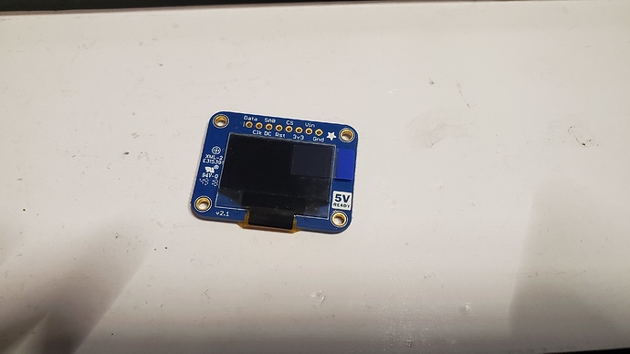
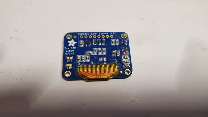
Suuuuuper thank you for the info on the OLED, because it turns out that I accidentally bought the right one (I think?). Does anything about this scream incompatible? Will have to learn what Address: 0x3C means. According to the back, it looks like there's an extra step for me: "For 12C Close SJ1/2", going to have to learn what that means too. Either way, thanks again!


#8

That display can communicate using either of two common serial protocols: SPI or I2C. To use it in I2C mode, you need to connect the two halves of SJ1, and the two halves of SJ2.
Easily done with two blobs of solder. But don’t connect SJ1 to SJ2.


#9

Oh it's as easy as that, then. Great, thank you!


#10

it might not work reliably with the adafruit oled. you might have to include a reset circuit (rc network) look it up in the OLED thread here on the forum


#11

Good to know, thanks. Would it work on its own if used in conjunction with the Teensy? If it has to be done in either case, I'll more than likely do the modification right onto the OLED like the user did here. It seems like the more surefire method.


#12

i see no reason that rc circuit shouldn't work with a teensy