Execution order (was: Phase cancellation issue?)


#1

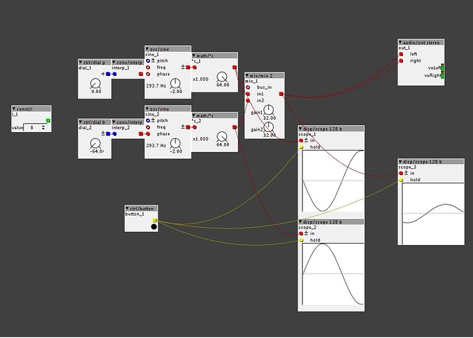
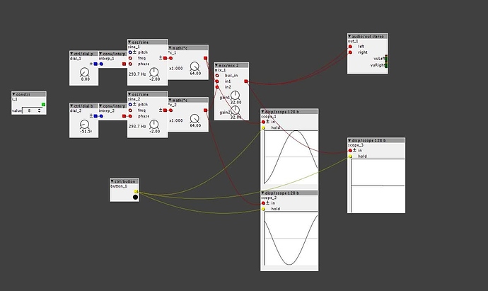
Or maybe not? I finally got my board last night (Yay!) and ive been working through some patches to get a feel for the environment. One thing I noticed this morning when working on some phase cancellation stuff was that a completely inverted sine doesn't actually cancel, and the only cancellation I cant get is around -290 degrees.

Am I missing something fundamental? I am using a linear interpreter to go from a bipolar dial into the phase inlet on a sine wave:

And then actual cancellation:


#2

From what I know I dont think it works like that. I dont really understand how the phase input works. But on Nord G2 for example it works as you described it. THe phase inlets has been discussed a bit in this thread:


#3

The nord works that way because that's how phase cancellation is expected to work. I think this is a bug, but I don't completely understand everything yet and I assumed it was due to me not quite getting how numbers are represented or how phase is intended to be used here.


#4

Yes, that is the way it is supposed to work. I understand the concept of phase, just not how it works in these objects. Will see what Johannes comes up with. The other thread insinuates that it might not be an easy job. Anyway, we will see what happens. Would be really nice if you could just connect it as you have done it. Phase control is important in some situations.


#5

I think in that thread he is specifically talking about adding phase to non sine waveforms, which is a bit of a pain in the ass. I think this bug may actually be in the mixer, since the phase looks correct in the two scopes. I'll look through the code this evening/ weekend.


#6

Could it be so because of axoloti's order of execution?


#7

Ace. yup that was it. Got carried away with patching before I went through all the tutorials. I knew it had to be something on my side! Thanks for all your help folks.


#8

Ah, yes you are right.


#9

@kausto is right, it is an effect of the execution order you're observing.

Personally I can work with the way it is. On the other hand I feel this is often not well understood. In many cases it does not have a significant impact except for a bit of performance.
The alternative is auto-optimizing execution order, but there are multiple solutions when feedback paths are involved, and then the outcome may depend on the phase of the moon. I believe the Nord Modular got its reputation that patches do not always sound the same came from execution order optimization magic.
Another way is a wire connection to just express execution order, I believe LabView takes this approach.
Without changing the behavior of Axoloti, connections with an implicit one-buffer-delay could be visually marked, but I haven't found a good way to express this visually.
Comments welcome!


#10

Thinking about this a bit last night @johannes. I definitely think you should do it magically behind the scenes, but then give feedback to the user that certain portions of the patch are using a more expensive path. You could update the UI based on patch compilation output. In this example I have added self feedback to tutorial #17. After compile the objects that are now part of the updated buffer path are outlined in red, and optionally you could highlight the patch cable that causes this:

Am I being to simple? Is there more data that the user should be privy to?


#11

Red color is used for warnings and errors usually. But in general this looks like working solution.


Subpatch: 16 step sequencer
#12

Yeah, it could technically be any color, but I sort of like red since you are now dealing with a patch that is a bit more expensive. You could reserve red for future use if you wanted.


#13

The issue is that magic results in multiple solutions and different results. The patch should express which solution will be selected, not just which solution was selected.

How do other environments deal with this? (I'm not talking about message-driven schemes like pd/max with hot/cold inlets and trigger object, but signal flow schemes)

  • Pd just complains "DSP loop detected (some tilde objects not scheduled)" as soon as you make a feedback connection, with an explicit delwrite~/delread~ as a solution.
  • Max 6.1 makes the connection but stops processing without any notification (?)
  • Max/gen~ (6.1) refuses to make a feedback connection without giving any other user feedback
  • Nord modular/G2: hidden magic, the user cannot see or impact which choice is made.
  • Others?

One solution could be a wire attribute ("buffered connection") that is set when creating a feedback connection, also visually distinguishable. But then there are also non-wired relations like tables and delaylines where execution order matters. Pd shows how to enforce execution order by creating dummy connections to a subpatch (3.audio.examples/G05.execution.order.pd) but I don't think this is very elegant.

Again, comments welcome!


#14

Does it make a difference how the 2 systems work? Axoloti has to be compiled and then runtime. G2 is always in runtime and always playable.

In G2 I have never encountered any issues related to order of execution. So there is surely some "magic" going on in the little red box :smile: But Axoloti I noticed it a few times. Anyway to me it is not really a problem. Just need to learn a bit more about it to be able to take it into consideration when patching.


#15

The G2 hides compilation (or call it linking) nicely. Adding an object to a patch restarts the patch - very quickly.

I have.


#16

Ahh, cool. Didnt know that about the G2 :wink: Guess a lot of things going on under the hood.

What issues you encountered on G2?


#17

Aha, I was having little glitches in a sequencer with gate time per-step and it turned out to be this! I know that it's based on positioning, but which bit of the object is considered its position? Is it the darker grey 'title bar'?
Some kind of indicator as to what the exact execution order will be based on current positioning would also be great along with an option to display the layout grid. Lines or dots in the background? Something to make the relative positioning explicit anyway.

Also, the user guide with 1.0.6 contains a typo regarding this - it says 'right to left' instead of 'left to right'. Luckily, the tutorial demonstrated this wasn't the case, but it did confuse me for a short while.