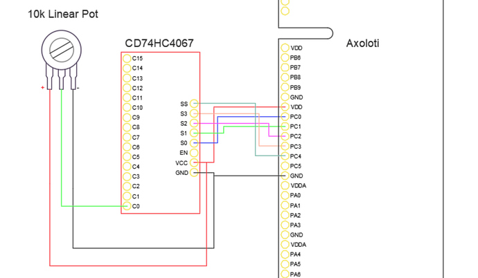
Since there is no object available for this chip in the community library, you'll have to program your own. The code in the following topic/post might be a good start: https://sebiik.github.io/community.axoloti.com.backup/t/adding-more-analog-inputs-using-a-multiplex-breakout-board/3805/15
This is how it works:
In the setup() method, you'll find this line: palSetPadMode(GPIOA,0,PAL_MODE_OUTPUT_PUSHPULL);. This means you are defining GPIOA/0 as an output. So you will need to set PC0, PC1, PC2 and PC3 as outputs, and PC4 as input. These pins will be used to select the channel you want to read from the multiplexer.
In the beginning of the loop() method you'll find this line: palWritePad(GPIOA,0,((i& 0x01) > 0));.This piece of code is writing a 0 or 1 to the GPIO A/0 pad.
So if you want to select channel 13 for instance, you'll have to write PC0 = 1, PC1 = 0, PC2 = 1 and PC3 = 1.
The value of the potentiometer connected to channel 13 can then be read with this method: palReadPad(port,pad); So in your case this will be palReadPad( GPIOC, 4 );
This is the list of GPIO on the Axoloti: https://sebiik.github.io/community.axoloti.com.backup/t/official-pin-out-ports-documentation/202/5

