"ccl" Field and Controller Range?


#1

Some of the MIDI CC hr objects have an additional field marked "ccl". Something of a MIDI noob here, what does this value do?

Also, what's the most straightforward way to make an object like an LFO or an oscillator cover the full span of its frequency range without going through a full turn on a MIDI controller knob? If the controller outputs 0 to 127 is there something in the maths set of objects that could force 127 to be reached part way through a knob turn, for example?


#2

there are two forms of the CC hr (14 bit)
the first form (i) (without) ccl follows the 'standard' convention the the LSB being the CC + 32.
i.e. CC 1 = most significant byte, CC 33 = least significant

the second form, allows you to say any CC is the least significant, since there are some synths etc, that dont follow the CC+32 convention.

second question ... the normal CC objects return +64 for 127 CC value (dont use the int forms unless you have good reason), so if you double it will reach it max at half way. then use a math/sat to ensure it doesn't go outside of the 'normal' range.
(that is if i understand your question correctly :smile: )


#3

You did, thanks for that!

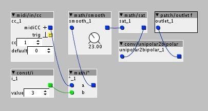
I have this which works well for controlling oscillators and LFO's etc:

I have eight controller knobs like this, and the only "unique" bit to each would be the midi/in/cc number and a patch/outlet. The rest stays the same for each knob. I could just copy and paste the above x 8 but is there a more elegant way of doing it? Keep one set of core objects and just multiply the midi/in/cc and patch/outlet objects? Suspect I'm making things overly complex... :confused:


#4

well, there is a CC any object, that receives all CCs, so with that you possibly could create a sub patch with a dial to select the CC.

one thing, i will say with the above, be careful of 'execution order'.
currently the above is executed...
cc, smooth, sat,outlet, u2b, i, multiply

i.e. the smooth, sat, is executed before the multiply ... so changes in the multiply, will only be reflect on the next execution cycle.
now, in practice, this is not going to make much of a difference BUT I would say its a 'bad habit' to get into, since, when you do more complex patches, i promise you, this is where the nastiest bugs can come from!

don't get me wrong, I think we all go through this, as we all like to make the patches quite compact/tidy on the UI... but unfortunately, this can change the behaviour of a patch... which is (imho) the flaw in graphical programming :wink:


#5

Is it? In my nooby way I thought I had it as this:

Incoming CC is multiplied by 3, that is then smoothed and "limited" to max/min values by math/sat, then changed to a bipolar signal in order to control an oscillator or LFO.

Not sure how you've arrived at the order you mentioned, is there an Axoloti internal execution order that trumps the order you put the objects in?

As I say, noob... :grin:


#6

the question is why do you think that...

the reason is, you believe (incorrect :wink:) that the execution order is determined by the wires.
i.e. you viewing data flowing down the wires, like electricity...

and thats the fundamental issue, it doesn't actually work like that... in some ways the 'metaphor' breaks down.
(there are other posts about why this is like it is, and how we can improve)

no... the way to think about it is a bit different.

every object is executed in turn, and 'presents' its data at the outlets, for connected inlets to pick up when they get executed.

so when is an object executed, well left to right, top to bottom ... or in 'reading order' (for the western world)

so in your example this means...
the CC object makes it data available to the multiply (good), the smooth object takes it data from the multiply BUT the multiply has not yet executed, so what value is that? well the value the multiply calculated on the last execution cycle.. (since its not run for this one yet)

its simple when you understand this, but can be counter intuitive.

why not follow the wires... well thats not always clear either. (again see other discussions)
and is why (partly) why max and reaktor have 'trigger'(order in reaktor) objects, which allow the user to influence the execution order. (ok its slightly different as max/reaktor are event based, which axoloti is not, and thats a completely different subject :wink: )

I will say, looking in the user guide, this is perhaps not clear enough, and an example would help alot....
actually, do you mind if I use your picture as an example, as I can then perhaps use my explanation, as a good example?
(as I said, we all go through this, you are not alone :smile: )


#7

Yes, exactly how I was expecting it to work. I've had far more experience with things like analogue modular systems and linear patches built in Max/MSP that follow the "electricity-through-wires" architecture and was following that principle...

Please feel free, I guess a lot of people will assume (wrongly) the same as me.

Just so I completely follow the logic (and so others can see), would you mind reordering the patch into the correct/logical execution order? I've attached it here:

ccmap.axp (2.2 KB)


#8

The easiest way to check order of execution is by looking.

BUT you can also check it by using the tablature button on your keyboard. Axoloti automatically selects next object in the order of execution when you use the tab button.


#9

Thanks but is that a Windows specific thing? Doesn't seem to work on my Mac.


#10

it works here on mac


#11

Interesting, got nothing here... I'm on 1.0.8 if that's relevant? Mac OS 10.11.4


#12

Sorry i Am still on 1.06 so No idea if it Works om 1.08