Axoloti for analogue Clock/Sync - Volcas, etc?


#1

Can the ax be used for Clocking/Sync'ing Volcas, Pocket Operators, etc? Ideally I'd like to send MIDI clock to the Ax and have an 1/8" output of a pulse signal that can provide analogue clocking. Would it be simple like a MIDI-clock-sync'd sample player with pulse signals loaded/played from a table?

Follow up question - could the extra analogue outputs on the GPIO possibly be used for this (PA4 and PA5)?


#2

sure..and much more than that


#3

Cool - any idea how to do it?


#4

for Axo 2 volca, get a minijack and test... probably, digital out it will work fine. sync input from pocket operators / volca / 8bitmixtape worked for me super good via audio input. Sure gpios will work good but before trying, I would check the voltage of the sync signal, just in case..


#5

Axo to volca via ditgital pin works fine.

For Volca to axo digital pin it would be wise to use some kind of protection circuit. There is one floating around here in the board with diodes, but I forgot the name of this specific circuit.


#6

maybe the easiest is to solder a midi out into the volcas. it is already on the board, you just have to solder a connecter somehow, there are tutorials on youtube. to sync midi_in on the axo is easy there are objects for it. in the patcher under help>midi>midi_clock_in you find a example patch. i am using the arturia beatstep pro as a clock, sync the axo with midi_in on the axo. with midi_out of the axo and a midi splitter i have now endless possibilities for other volcas and what not with midi, and the beatstep spits out lots of CV and Gates at the same time.


#7

I can really recommend this one too. Like this you can also feed analog clock to volca an receive Midi clock from volca to axoloti.


#8

Thanks for the replies guys. I actually used the Volcas as a well-known example, but i don't actually use them! So the MIDI idea will not work.
I use Pocket Operators and a Folktek Mescaline, all of which use an old-school pulse sync signal for clocking. My plan is to connect the OP1 via the Ax's USB host, receive the MIDI clock from that, and feed out of the Ax an analog pulse sync. The OP1 has this functionality built in, but when you use it's pulse sync via it's own output that means you lose stereo feed, which I don't want to do.

So, my understanding is that PA4 and 5 are actually analog outputs that are used for CV - would these not be perfect for my needs, without a protection circuit, etc? Any thoughts on how this could function?

I'm thinking something along the lines of midi/in/clock > Waveplayer loaded with pulse signals, triggered when clock is high > GPIO/PA4


#9

You don't need analog pins you can use any of the digital pins. Digital in that senes means they only send On = 3.3V and Off = 0V. A clock pulse is only a short OnOff for every clock tick.

If axoloti SENDS the pulses it should be fine.


#10

Ahhhhh right I hear you - would the digital on/off function as a decent sync? I won't be in front of my Ax again for another week, hence not being able to test myself... Anyone want to test this for me, pretty please?


#11

Hey guys,

Wondering if someone can help me out here - I made the journey out to my jam space to grab my Ax so I can have a decent crack over the weekend, and I cannot get my head around how this can function.

Firstly, what I would like to do:
1. Use my OP1's MIDI out into the Ax USB Host port.
2. Receive clock from the OP1. Have this switch on/off depending if the OP1's main tape/sequencer is playing
3. CHange this clock information into a pulse/sync click/whatever will function
4. Send this out to be received by something that uses sync in (Pocket Operators, Modular, Volcas without Midi)

I've tried a few different methods now, including using the @DrJustice MIDI rx module to drive an osc/vca combination. No dice.
I've also tried setting up a sequencer based on some of the library patches, to then drive an oscillator. this doesn't seem to work either. Any use of an Env then affects the tempo of anything that is being spat out. All I need is a simple sync pulse that is in time with the MIDI clock - am I missing something really simple here? Ive been through every single clock module trying to make this work

I'm tearing my hair out trying to understand how this can actually function but I feel it's way beyond my coding/logic/DSP knowledge. Can anyone help me with a potential patch here? @thetechnobear ?


#12

Using drj/midi/clock_rx and gpio/out/digital you should be able to receive MIDI clock and pass on sync pulses.

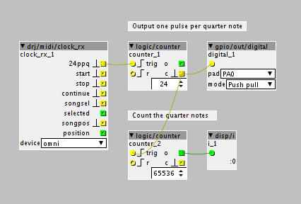
The example patch below divides the incoming MIDI clock by 24 to get a pulse per quarter note and then outputs this on an IO pin. It also counts the quarter notes just for diagnostics. The IO pin output voltage is 3.3V which may not be enough to drive some trigger/clock inputs directly (someone else can probably give some more detailed info on that).


#13

ahha! This patch works (sort of)! Even just jumping between PA0 and my small modular makes it perfectly receive the click!

The problem is actually the Pocket Operators - the signal mustn't be strong enough. I have a Bastl Klik for this purpose (amplifying a sync pulse), but of course it only works with analog signals, and when receiving the digital it produces high only - no low. Can this patch be changed to an analog output? Like PA4/5? What would be the best way of doing this?

While I'm at it, the other problem I'm facing: Ax received MIDI clock from the OP1 regardless of if the main sequencer (tape mode) is playing or not, which makes sync pretty difficult. Is there a specific type of MIDI message from the OP1 I should use to start/stop/restart the clockrx each time?


#14

Good - we're getting somewhere :slight_smile:

Regarding the Pocket Operator sync problem, using an analogue output will most likely not help - both digital and analogue outputs are 3.3V max. Anyway example patch below show how to use both types of output, so you can test. Also, it's worth trying to change the digital output "mode" to "Open drain" - In synth terms, "Push pull" should be what is called "V-trig" (V for voltage) and "Open drain" should be S-trig (S for switch).

As an extreme measure you could amplify the trigger signal by hooking up a 5V logic gate, or an op-amp, to use as an amplifier between the digital out pin and the device to be triggered (I don't think that should be needed in most cases).

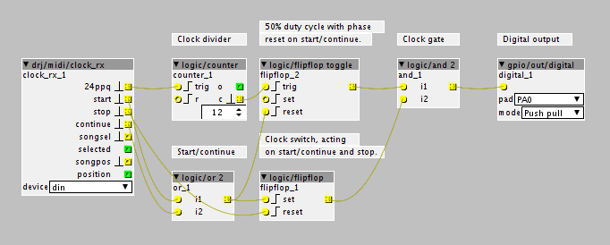
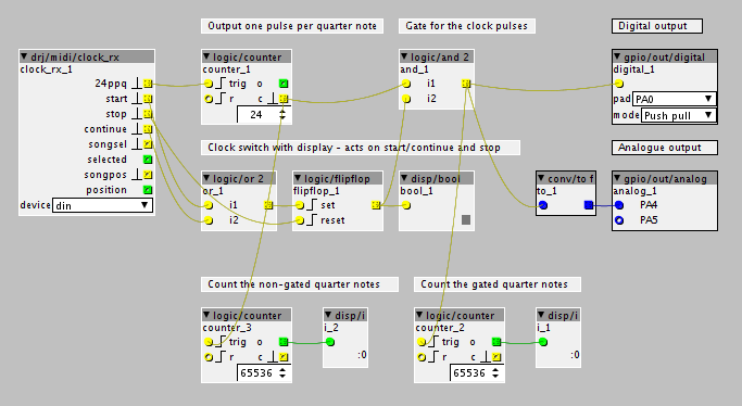
As for your second issue, the clock can be started and stopped using an AND gate. This gate is controlled by the start, stop and continue signals, which drives a flip-flop to enable and disable the clock. This is implemented in the patch below, and works fine when tested with another synth here. For this to work, the OP1 sequencer needs to send the MIDI start and stop messages (and optionally the continue message) - most gear with sequencers do that, so there's a good chance it'll work.

The patch overview and the actual patch is attached below. It contains diagnostic counters for the gated and non-gated sync pulses.
test_midi_clock_rx_2.axp (4.6 KB)

#15

This is awesome man, thank you so much! The logic side of things is definitely where my knowledge dries up, looking forward to giving this a crack over the weekend!


#16

Hey @DrJustice I just got around to trying your patch - the stop/start functionality works perfectly! Only problem is that the output from PA4 was super low - barelu triggering my Bastl Klik. I just whipped out my old Fluke to measure the voltage coming from the pins, and sure enough it's only reading a very very minimal amount (0.01v). I have a feeling I may have attached to the GPIO incorrectly - I have attached to PA4 and GND with two wires then connected to an 1/8" for sync. Do I need to incorporate the VDDA to correctly route voltage to PA4 or the digital out?


#17

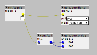
Unfortunately I have none of my instruments at hand, so I can't measure anything. When you measure short pulses (0.0003s in this case) with a multi meter, you'll not see much since the pulses are usually too narrow for the meter to react. If you try the patch shown here, you can use the switch and measure the IO pins in a steady state (perhaps you already tried that):

For the analogue outputs, PA4 and PA5, you should not need anything extra, just the Px pin and GND. Make sure that the pad selection on the digital out isn't set to PA4 since that would cause a configuration conflict.

Perhaps it would be better to use a digital output for the sync pulse anyway, saving the analogue outputs for when you need a varying voltage(?)


#18

Just got around to testing this patch - the direct patch using the toggle definitely worked and read an almost perfect 3.29 v. However, still no love getting it to sync the Pocket Operators.

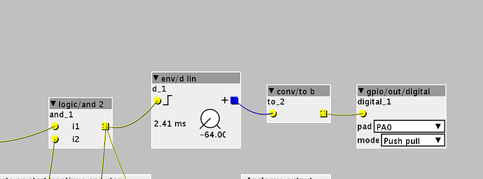
THAT SAID. Something weird just happened. I added an env/d lin and then a conv/to b between the logic/and object and the digital output and VOILA, it worked! only problem is that it changes the time of the sync, as the fastest it will go is 2.41ms. Any thoughts on a) Why TF this would happen? and b) an efficient way of doing this so the timing is back on track?

Thanks for all your help so far @DrJustice !


#19

Presumably signal shaping in effect - some devices can cope with any pulse width, others demand a 50:50. Your input appears to be far enough off the ideal to fail on some devices. Patch in a scope, and the difference ought to be visible.


#20

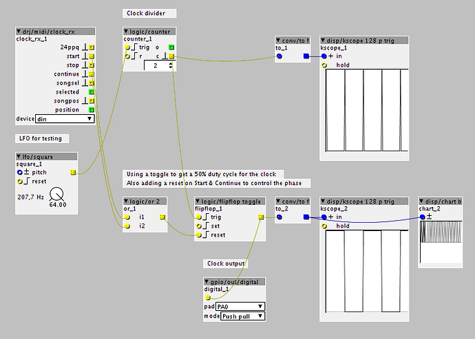
From the envelope trick you tried and the good point made by @sevo, here's how you can make the narrow clock pulses into a 50% duty cycle square wave. You need to divide the clock by half of what you do for straight pulses since it uses a logic toggle function - so e.g. use a divider of 12 instead of 24 to get quarter notes. The logic toggle also uses a reset triggered by the start and continue signals to make sure the phase is right, i.e. that the pulse is positive on the first clock.

(In the example patch I use an LFO instead of the 24ppq signal just for convenience in testing)

Edit: the clock gate has been omitted in this example - if this 50:50 clock works I can post a complete sync example with all features so far if you want.

test_midi_clock_rx_3.axp (3.7 KB)

Edit 2: Might as well attache the complete midi clock to sync example for completeness sake:

midi_clock_to_sync.axp (3.2 KB)