Assigning hardware pots to objects with no connection points


#1

Not really sure how to phrase this question, but here's a shot at it:

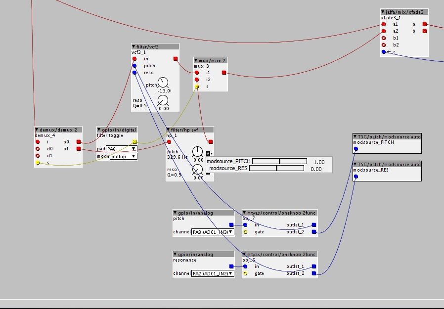
A lot of objects, for example a delay, will have connection points for mix, time and repeats, so you're able to connect virtual or real pots to control said parameters. But, every now and then you come across some objects that don't, and if you try opening them as patch patcher you won't always get to see the building blocks and copy them to your main patch in order to add controls that are external to the object itself. For me it was a HP filter. I really preferred that filter to the others I found, but it had no connection points for the cutoff frequency or resonance. If I try to open up the object it will only give me information on who made it etc.

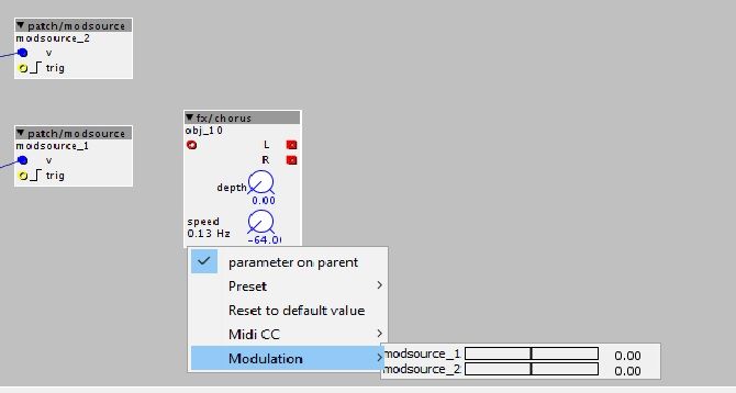
Basically, is there a way to add connection points to objects like this one so that I can control the parameters with hardware pots? I have cut off the MIDI board on my Core, so assigning MIDI to the virtual pots already located within the original object is not an option (unless it is?).

Bonus question: in my main patch I have a toggle that switches between two delay objects, basically rerouting the signal, and I use the same knob to control time on both of the delays, but one of the delays' time knob is "wired backwards" within the object, so CCW is longer delay times. This makes it so I get a big jump in delay time when switching over from one delay to the other. Is there a way to invert the parameter of one of the delays, or how it reads the values of the pot?

Thanks!


#2

if there is a knob you can create a modsource object and connect your pot output to that. you can then simply add the modsource to said knob. (via right click on the knob)

as for your second question:

just invert the signal from the pot before you send it to the second delay. there are bipolar inv objects, but also unipolar inverters.


#3

hmmm, I'm a bit stuck now. I've added the two modsource objects and gone from gpio/in/analog (the pots) to each of the modsource objects, but when I Iright click on the pots on the chorus (in this case) I can only see the mod sources, but I can't click them (nothing happens when I do)


#4

Also tried all the 'inv' objects I could find to reverse the direction on the time knob, but it didn't work :thinking: What's the object name?

@lokki halp!


#5

drj/math/inv_pos

This worked for me on Axocontrol pot.


#6

you should probably use TSG/modsource auto, it will update the value automatically. with the one you use now, it will only update the modulation target when the trig input changes.

you should be able to move the slider with the mouse once you click on it.


#7

Thank you both very much! I will give it a shot tomorrow!


#8

I'm still not making it work.

So, first I've got the signal going into the demux2, and there's the the gpio/in/digital making it so that I can select either one of the filters (vcf3 and hp svf) via the toggle. Then I've got the analog ins for controlling pitch and res on the vcf filter. So far, so good. Then I want to control the pitch and res on the svf when I've toggled over to that filter, so I got two TSG/patch/modsource_auto objects. They're connected to the gpio/in/analog objects of the same pots that control pitch and res on the other filter. When I right click on one of the knobs, it shows both modsources. I can't click them to select which one I want to use on that particular knob. I can move the sliders, but nothing happens when I try moving the knobs when the patch is live. I don't even understand how the software is supposed to know which modsource to use on which knob when I'm unable to select them from right-clicking the knob, aka assigning the mod source to the knob I want to use. I've tried going straight from the gpio/in/analogs to the modsources, and I've tried going from both outlet 1 and 2 of the oneknob2func object.

What am I missing here?

@lokki


#9

first i think you don't need the 2func thing at all, or what are you trying to achieve with it? just connect the analog out to both the vcf inlets and the modsource.

as for the sliders:

you can assign all modsources to all pots. so clicking on a pot and showing the modsources gives you this menu you are seeing. you then adjust the moddepth with this slider. so on your pitch knob you want to set the modsource that connects to your pitch analog in to 64 and the other to zero. on the reso knob you do the inverse. i don't think you can see the parameter change in the patcher, but you should hear it!


#10

Oh, that makes a whole lot of sense, haha. Worked like a charm! Thnx!


#11

or..
1. embed the hp SVF module
2. add two inlets (blue fraction inlets) called "pitch" and "reso"
2. go to k-rate code and add "+inlet_pitch" and "+inlet_reso" at the spots where it tells you it uses the param_pitch and param_reso values:
(ok, for the resonance I did add an extra function: __USAT(.......,27),
which keeps the values safe from wrapping when the values add up and are shifted beyond a 32 bit value)
so, just copy and paste to the right lines in the code:

int32_t damp = (0x80<<24) - (__USAT(
param_reso+inlet_reso,27)<<4);

MTOFEXTENDED(param_pitch+inlet_pitch,alpha);

As you can see, adding inputs to a module is fairly straight forward.
Just go through the code to find the places where "param_......" is used and add "+inlet_....." where the dotted line is the name of the parameter.
There are a few things to think about though (ps, the text editor overhere doesn't show the code in the right way when I use it in a single line, so I needed to use multiple lines. In the axoloti you can just write it as a single line of code)

-values that, when added up, might go too high for a 32bit value, losing bits in the math process. You'll need to clip these->

code:
__USAT(
param_reso+inlet_reso,27)

which means:
a unipolar saturate/clipping to 27 bits, which is the range of a normal unipolar knob

code:
__SSAT(
param_pitch+inlet_pitch,28)

which means a bipolar saturate/clipping to 27 positive and 27 negative bits, which is the range of a normal bipolar knob.

-in some cases you'll need to put the summation in brackets "(...)" to make sure it's being added to each other before the next calculation is done, eg. when a parameter value is multiplied->
if it says:
x=param_P*7+param_Q
x=(param_P+inlet_P)*7+param_Q+inlet_Q;

note btw, that when putting the summation between __USAT(......,27) or __SSAT(.....,28), you don't need those extra brackets..

last note..
some of the controls (gain x1, gain x16 and some of the envelope time knobs) use a different range and scaling which makes it impossible to "just add" an inlet value to the parameter value. For this other ways should be used to add external control, but this is a bit harder to explain if you haven't coded yet and depending on which kind of parameter you have and what it's being used for)


#12

btw. looking at your picture, there is also an important principle for patches that you should keep track of.

Always try to build your patches from top to bottom and left to right.
Each time a connection is made from a lower module to a module above it (or from right to left when the modules are on the same height), this will introduce a 16 sample delay.
The part that we can see here on the picture already introduces 32 samples delay, as you go up twice, once from the demux to the vcf3 (and from hp svf to mux) and then from the mux to the xfade.


#13

i think this is the way people should be taught to add mod/inputs to objects. it is so much more efficient than going the "modulation source" route and also shows people how easy it is to modify or add objects. i might try and do a little cleaned up write up on this for the user guide section based on your reply @SirSickSik.


#14

Definitely. It can look daunting at first if you don't know code (like I didn't) but it's easy once you try, and so useful.


#15

I jumped in as a complete noob as it comes to coding..
ok, I had my years of synthesizers using synthedit and owning quite a bunch of hardware synths, but "coding" was completely new for me.
But if you look to the simple modules, you can quickly find out how it all works, just by looking at the code.
for example, my first thing was to adjust the sine oscillator to actually have the right frequency modulation index depending on it's frequency.
So I embedded the sine oscillator to look at it's code:
-ok, there's something like "Phase+=freq"...
don't know the += thingy, but ok.. I know what a phase of an oscillator is and I know what a frequency is.
so probably, here, some value called "freq" is added up to some value that is supposed to be the phase of an oscillator.
-next problem.. to my knowledge, the phase of a sine is going from 0 to 1 and putting the "freq" value into the display, it shows me quite a big value, far beyond 1.. so probably there's some scaling going on. anyways, next line..
-"SINE2TINTERP( blablablabla)", ok, whatever, seems to be some sine "calculator" (didn't know what a table was atm)
so, whatever that "phase" value's maximum is going to be, it seems to play one sine as it goes round.
-there are some weird marks before that "r".. let's remove them... ah ok, this somehow changes the amplitude (bit shifting)

-well, ok, I've got some phase, which has some "freq" value being added every sample, then somehow this phase gets converted to a sine using that SINE2TINTERP(blabla,bla) formule, "shift" it down a bit, and I get a sine wave out of that.
-let's screw this puppy up!
-I want to multiply the frequency of the oscillator with the modulator, before I actually add it to the frequency.. how do I multiply something?? -> multiply module!
-open up multiply module, voila: something that is kind of familiar: ___SMMUL(bla,bladibla), I at least recognize "MUL" as being something to multiply something.. let's copy paste that shit!
-enter "freq" instead of "bla" and "inlet_freq" instead of "bladibla" and... we got a weak FM modulation....
-ah, there were these weird marks making the amplitude weaker.. perhaps, if I use them the other way, it might make it louder.. ah!
-"bitshift" the shit with 9 and you'll have a wonderful frequency indexed fm modulation :slight_smile:

that was bit of a round up for my first module a couple of years ago.
just start with the simplest of modules and work your way up from there.
A lot of my modules start off with the sine module, the 6dB/biquad/svf filter, delay module or counter.
These modules are often a very good starting point to have a basic layout and to build on.
Just change something and see what happens..
-maybe a simple error.. just look at the error and find that line of code in those 10 lines your wrote..
-wooooooow, what the f*^&$&k a long red text.... probably forgot to add one of the ( ) { } pairs somewhere....
-sweet it goes live, wtf is that output... check your maths...
-sweet it goes live, and it actually works..... next code! :stuck_out_tongue: