A physical switch doesn't act in the software (solved 🤘🏻)


#1

Hi,
I'm a new in the axoloti community but I've some programming skills derived from Nord Modular and Reaktor softwares.

I'm planning to build a physical multi fx unit to process different incoming signals (piezos and audio in) with axoloti board.

At the moment the structure is the seguent:
Audio in/piezo pickup - delay - filter - reverb (also a pitchshifter with pre/post delay switch)

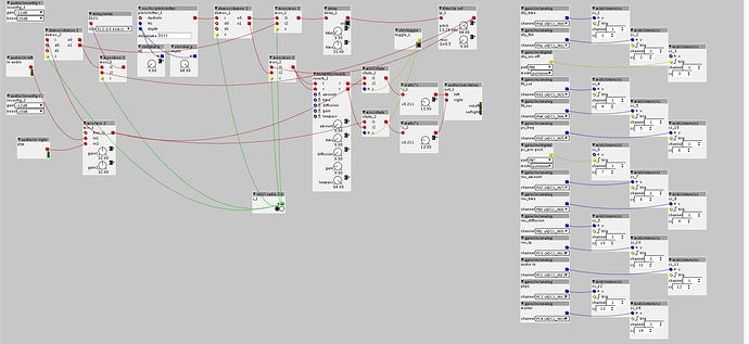
I've soldered 12 knobs and 2 switches to the gpio ports and assigned midi CCs to all the parameters I want to control. Knobs acts correctly with response in the software and audio result but switches do not. Here's my patch, someone knows what's missing?
Thanks a lot

Ps. This patch isn't updated with logic/change between gpio/in and midi/intern/cc


#2

Please tell us how you connected the switches. You configured the inputs as pulldowns. So I assume the switches are wired towards 3,3V?


#3

Yes it is, one pin to vdda and one to the pb06 ( pb07 for the other switch)


#4

How have you made the connection, with solder ? if so check your solder joins.
Have you tested the switch to ensure it works ? maybe its faulty.


#5

Yes, I solder it and tested with scope, it works properly, I think there is a problem in my patch but I don't know where it is :confused:


#6

You connected the logic level from gpio/in/digital to the trigger input of midi/intern/cc, while the value inlet is left unconnected, that means it will only transmit zero when you press your button.
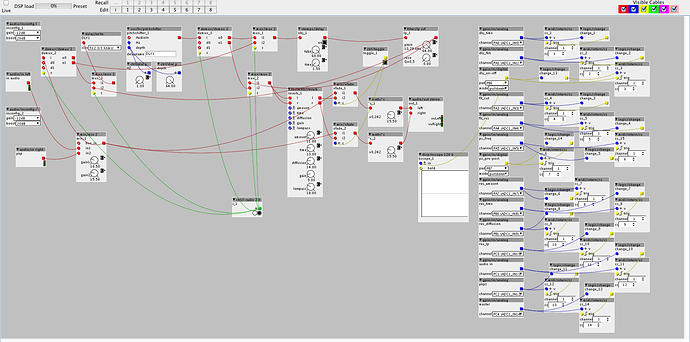
You should trigger midi/intern/cc when the logic level from gpio/in/digital changes, use logic/change to detect changes and generate the trigger for midi/intern/cc, and connect the logic level to the v inlet of midi/intern/cc.


#7

Thank you, I supposed that it was a problem of this type, if I remember correctly I've already tried this trick, testing it with a midi controller it works but apparently after soldering the switch something went wrong...anyway I'll try again and let you informed


#8

Patch updated as from your suggestion BUT unfortunately it works only from OFF to ON and not vice versa :(


#9

The trig inlet of midi/intern/cc should come from the logic/change, the v inlet from gpio/in/digital, you have those swapped around for the buttons.


#10

Amazig!!! :smiley: Now it works correctly!! Thank you very much big boss :metal:🏻